


Steel Beams
Q355B H-Beams: GB/T 1591 Grade, Sizes & CEV
Q355B H-Beams: Specify the Hot-Rolled Material Route
Q355B is the hot-rolled low-alloy high-strength grade in GB/T 1591-2018, applied here to parallel-flange H-sections. Its first thickness band has 355 MPa minimum yield, 470–630 MPa tensile strength and a 34 J longitudinal Charpy requirement at +20 °C. Gangsteel builds a Q355B H-section enquiry around the delivery route, the four section dimensions and the required inspection evidence, not a claim that all 355 MPa steels are interchangeable.
This combination is relevant to strength-governed columns, industrial frames, truss chords and heavily loaded beams. A higher grade can reduce required steel area, but it does not make an unchanged beam stiffer or remove lateral-torsional buckling. The old designation Q345B is useful when interpreting drawings; a Q345B certificate is not automatically a GB/T 1591-2018 Q355B certificate.
| Order decision | Required identification | Boundary |
|---|---|---|
| Material and route | GB/T 1591-2018 Q355B, hot-rolled | Not a Q355N or Q355M chemistry/condition table |
| Geometry | Full H × B × tw × tf, GB/T 11263 edition | Not an EN HE section or ASTM W shape merely because it looks similar |
| Impact direction | Longitudinal by default; transverse by agreement | 34 J longitudinal and 27 J transverse are not one universal energy |
| Test location | Material-standard provisions and GB/T 2975 | Nominal thickness and specimen-preparation rules must match the delivered section |
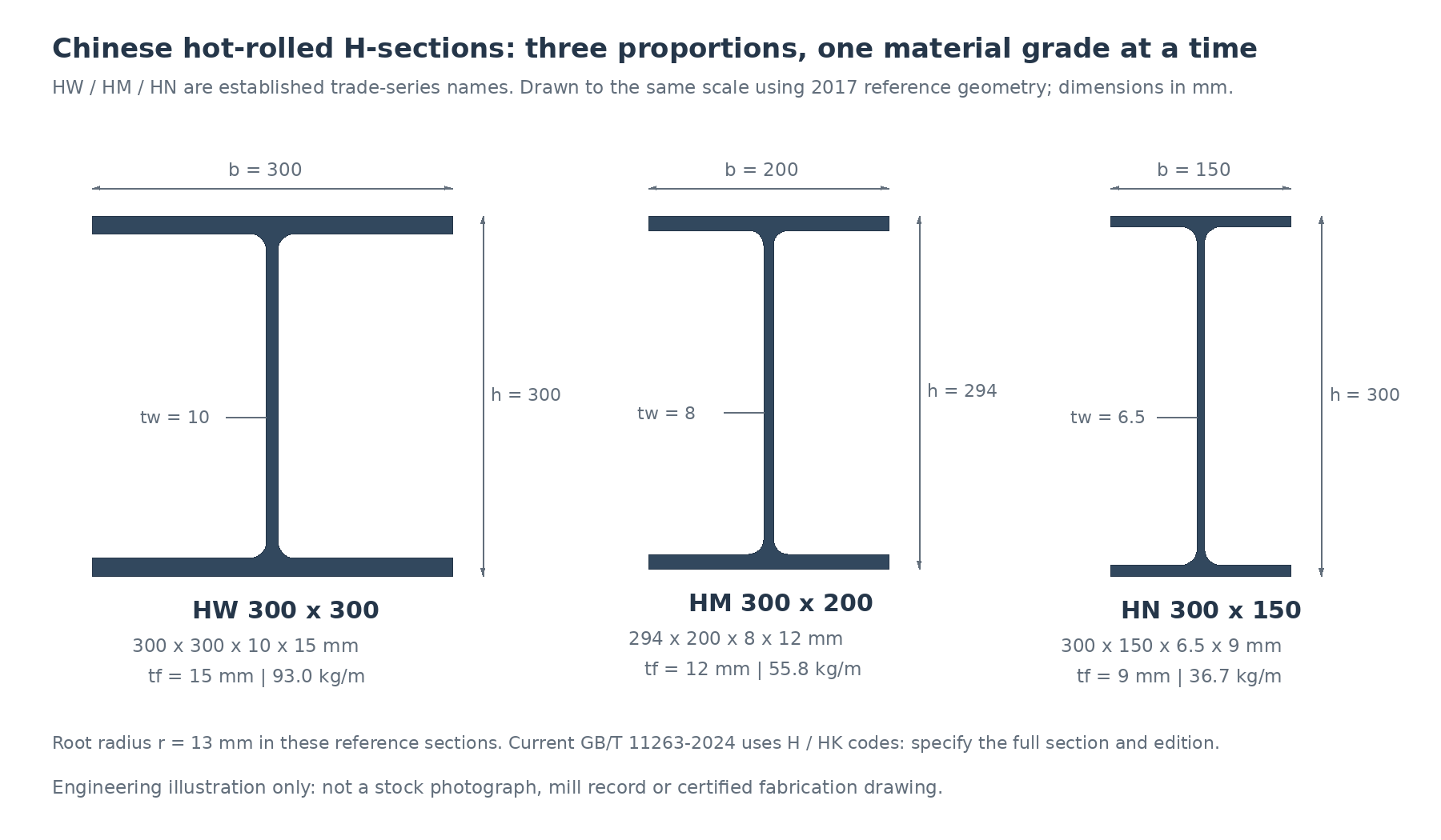
Current H/HK Designation and Established HW/HM/HN Sizes
GB/T 11263-2024 has been effective since 1 May 2025 and replaces the 2017 edition. It uses H and HK categories, rather than making HW, HM and HN the current formal classification. Those older names remain common on drawings and enquiries. The size tables here deliberately retain the established HW/HM/HN reference geometry and 2017 theoretical masses; they are not a reproduction of the revised 2024 appendices. On a current order state the full H × B × tw × tf dimensions, the dimensional edition and its mass basis. Do not settle a 2024 order using an older kg/m table without agreement.
Use the older series names as a search and drawing aid: HW is broad-flange, HM intermediate and HN narrow-flange. They describe proportions, not quality grades. A nominal HM 300 × 200 reference has an actual depth of 294 mm; confusing the trade call with a measured 300 mm depth can cause a connection mismatch.
HW: Wide-Flange Reference Sizes
| Reference section | h mm | b mm | tw mm | tf mm | kg/m | ReH MPa, flange-band reference | CEV max, flange-band reference |
|---|---|---|---|---|---|---|---|
| HW 100×100×6×8 | 100 | 100 | 6 | 8 | 16.9 | 355 | 0.45 |
| HW 125×125×6.5×9 | 125 | 125 | 6.5 | 9 | 23.6 | 355 | 0.45 |
| HW 150×150×7×10 | 150 | 150 | 7 | 10 | 31.1 | 355 | 0.45 |
| HW 175×175×7.5×11 | 175 | 175 | 7.5 | 11 | 40.4 | 355 | 0.45 |
| HW 200×200×8×12 | 200 | 200 | 8 | 12 | 49.9 | 355 | 0.45 |
| HW 250×250×9×14 | 250 | 250 | 9 | 14 | 71.8 | 355 | 0.45 |
| HW 250×255×14×14 | 250 | 255 | 14 | 14 | 81.6 | 355 | 0.45 |
| HW 300×300×10×15 | 300 | 300 | 10 | 15 | 93 | 355 | 0.45 |
| HW 300×305×15×15 | 300 | 305 | 15 | 15 | 105 | 355 | 0.45 |
| HW 350×350×12×19 | 350 | 350 | 12 | 19 | 135 | 345 | 0.45 |
| HW 400×400×13×21 | 400 | 400 | 13 | 21 | 172 | 345 | 0.45 |
HM: Medium-Flange Reference Sizes
| Reference section | h mm | b mm | tw mm | tf mm | kg/m | ReH MPa, flange-band reference | CEV max, flange-band reference |
|---|---|---|---|---|---|---|---|
| HM 148×100×6×9 | 148 | 100 | 6 | 9 | 20.7 | 355 | 0.45 |
| HM 194×150×6×9 | 194 | 150 | 6 | 9 | 29.9 | 355 | 0.45 |
| HM 244×175×7×11 | 244 | 175 | 7 | 11 | 43.6 | 355 | 0.45 |
| HM 294×200×8×12 | 294 | 200 | 8 | 12 | 55.8 | 355 | 0.45 |
| HM 340×250×9×14 | 340 | 250 | 9 | 14 | 78.1 | 355 | 0.45 |
| HM 390×300×10×16 | 390 | 300 | 10 | 16 | 105 | 355 | 0.45 |
| HM 440×300×11×18 | 440 | 300 | 11 | 18 | 121 | 345 | 0.45 |
| HM 482×300×11×15 | 482 | 300 | 11 | 15 | 111 | 355 | 0.45 |
| HM 488×300×11×18 | 488 | 300 | 11 | 18 | 125 | 345 | 0.45 |
| HM 582×300×12×17 | 582 | 300 | 12 | 17 | 133 | 345 | 0.45 |
| HM 588×300×12×20 | 588 | 300 | 12 | 20 | 147 | 345 | 0.45 |
HN: Narrow-Flange Reference Sizes
| Reference section | h mm | b mm | tw mm | tf mm | kg/m | ReH MPa, flange-band reference | CEV max, flange-band reference |
|---|---|---|---|---|---|---|---|
| HN 100×50×5×7 | 100 | 50 | 5 | 7 | 9.3 | 355 | 0.45 |
| HN 125×60×6×8 | 125 | 60 | 6 | 8 | 13.1 | 355 | 0.45 |
| HN 150×75×5×7 | 150 | 75 | 5 | 7 | 14 | 355 | 0.45 |
| HN 175×90×5×8 | 175 | 90 | 5 | 8 | 18 | 355 | 0.45 |
| HN 198×99×4.5×7 | 198 | 99 | 4.5 | 7 | 17.8 | 355 | 0.45 |
| HN 200×100×5.5×8 | 200 | 100 | 5.5 | 8 | 20.9 | 355 | 0.45 |
| HN 248×124×5×8 | 248 | 124 | 5 | 8 | 25.1 | 355 | 0.45 |
| HN 250×125×6×9 | 250 | 125 | 6 | 9 | 29 | 355 | 0.45 |
| HN 298×149×5.5×8 | 298 | 149 | 5.5 | 8 | 32 | 355 | 0.45 |
| HN 300×150×6.5×9 | 300 | 150 | 6.5 | 9 | 36.7 | 355 | 0.45 |
| HN 346×174×6×9 | 346 | 174 | 6 | 9 | 41.2 | 355 | 0.45 |
| HN 350×175×7×11 | 350 | 175 | 7 | 11 | 49.4 | 355 | 0.45 |
| HN 400×150×8×13 | 400 | 150 | 8 | 13 | 55.2 | 355 | 0.45 |
| HN 396×199×7×11 | 396 | 199 | 7 | 11 | 56.1 | 355 | 0.45 |
| HN 400×200×8×13 | 400 | 200 | 8 | 13 | 65.4 | 355 | 0.45 |
| HN 446×199×8×12 | 446 | 199 | 8 | 12 | 65.1 | 355 | 0.45 |
| HN 450×200×9×14 | 450 | 200 | 9 | 14 | 74.9 | 355 | 0.45 |
| HN 496×199×9×14 | 496 | 199 | 9 | 14 | 77.9 | 355 | 0.45 |
| HN 500×200×10×16 | 500 | 200 | 10 | 16 | 88.1 | 355 | 0.45 |
| HN 546×199×9×14 | 546 | 199 | 9 | 14 | 81.5 | 355 | 0.45 |
| HN 550×200×10×16 | 550 | 200 | 10 | 16 | 92 | 355 | 0.45 |
| HN 596×199×10×15 | 596 | 199 | 10 | 15 | 92.4 | 355 | 0.45 |
| HN 600×200×11×17 | 600 | 200 | 11 | 17 | 103 | 345 | 0.45 |
| HN 625×198.5×13.5×17.5 | 625 | 198.5 | 13.5 | 17.5 | 118 | 345 | 0.45 |
| HN 630×200×15×20 | 630 | 200 | 15 | 20 | 133 | 345 | 0.45 |
| HN 700×300×13×24 | 700 | 300 | 13 | 24 | 182 | 345 | 0.45 |
| HN 800×300×14×26 | 800 | 300 | 14 | 26 | 207 | 345 | 0.45 |
| HN 890×299×15×23 | 890 | 299 | 15 | 23 | 210 | 345 | 0.45 |
| HN 900×300×16×28 | 900 | 300 | 16 | 28 | 240 | 345 | 0.45 |
| HN 1000×300×19×36 | 1000 | 300 | 19 | 36 | 310 | 345 | 0.47 |
The yield column uses nominal flange thickness as a selection reference, not the overall section depth. Final material acceptance follows the ordered material standard and the applicable GB/T 2975 sampling location and specimen-preparation thickness. Depth, width, thickness, straightness, flange squareness and web centring are inspected against the ordered GB/T 11263 edition, not against rounded catalogue dimensions.
The CEV column uses the reference flange-thickness band: 0.45% up to 30 mm, 0.47% above 30 mm in the selected range. HN 1000 × 300 × 19 × 36 is the selected example crossing that chemistry boundary; it still uses the 345 MPa yield band to 40 mm. Yield and carbon-equivalent boundaries are different tests and must not be merged into one thickness rule.
Heat Chemistry: Do Not Borrow a Q355N, Q355M or Plate Table
| Element | Requirement | Section-specific qualification |
|---|---|---|
| C | 0.24 | For nominal t >30 mm: 0.22 max; sections above 100 mm may be agreed separately |
| Si | 0.55 | Low-Si galvanizing orders require review of the associated CEV provisions |
| Mn | 1.60 | Not an assumed microalloying recipe |
| P | 0.035 | Sections/bars may use the standard allowance of +0.005, i.e. 0.040 |
| S | 0.035 | Sections/bars may use the standard allowance of +0.005, i.e. 0.040 |
| Cr / Ni | 0.30 each | Heat-analysis maxima |
| Cu | 0.40 | Heat-analysis maximum |
| N | 0.012 | Guarantee and nitrogen-binding exceptions apply |
| Nb / V / Ti | No mandatory addition in the Q355 Table 1 row | Other additions by agreement must be reported |
The nitrogen provisions allow analysis to be omitted when guaranteed; nitrogen is not restricted under the stated nitrogen-binding practices, for example sufficient soluble or total aluminium, with the applicable certificate reporting. The 0.040% section allowance for P and S is not the base plate limit, and it should not be hidden by publishing only a plate chemistry row. A buyer needing tighter P/S should write those limits explicitly.
| Nominal t mm | CEV max % | Application |
|---|---|---|
| ≤30 | 0.45 | Most selected H-section flanges |
| >30–63 | 0.47 | Includes the selected 36 mm flange |
| >63–150 | 0.47 | Heavier sections, outside the selected dimensional table |
| >150–250 | 0.49; sections/bars allowance to 0.54 | A special heavy-product enquiry, not a claim of this size range |
CEV = C + Mn/6 + (Cr + Mo + V)/5 + (Ni + Cu)/15, using mass percentages. These are specification limits, not actual delivered CEV values and not a preheat chart. Low-silicon galvanizing variants have associated standard footnotes; settle the silicon target and the matching CE requirement before quotation rather than keeping an unconditional generic cap.
Product Analysis and Certificate Review
| Evidence | Acceptance treatment |
|---|---|
| Heat analysis | Compare the actual ladle results with the hot-rolled Q355B limits, footnotes and any tighter order limits |
| Finished-product analysis | Use the applicable GB/T 222 permissible deviations; do not add a blanket tolerance to every element |
| Delivery route | Check the certificate says the intended condition; normalized and thermomechanical routes have different chemistry and CE tables |
| Additional elements | Check agreed additions and reported nitrogen-binding practice; do not assume mandatory Nb/V merely from the word HSLA |
A material declaration or plate certificate for the same grade cannot establish the analysis of the H-section heat. If independent product analysis is required, include sampling, test method and the applicable limits in the inspection plan. The reference chemistry above is not a set of invented “typical mill results”.
Tensile Properties and the +20 Degree Impact Quality
| Nominal t mm | ReH min MPa | Rm MPa | A min % |
|---|---|---|---|
| ≤16 | 355 | 470–630 | 22 |
| >16–40 | 345 | 470–630 | 22 |
| >40–63 | 335 | 470–630 | 21 |
| >63–80 | 325 | 470–630 | 20 |
| >80–100 | 315 | 470–630 | 20 |
| >100–150 | 295 | 450–600 | 18 |
| >150–200 | 285 | 450–600 | 17 |
| >200–250 | 275 | 450–600 | 17 |
At +20 °C the specified full-size impact energy is 34 J longitudinal, or 27 J transverse where transverse testing is agreed. Test direction is part of the result. Thin section elements may require sub-size specimens under the standard’s sampling and energy provisions; specify the reporting basis rather than demanding an impossible full-size specimen from a thin flange. B is a test quality, not a guarantee that the beam is suitable at every sub-zero service temperature. Use the project’s fracture assessment to select a colder quality when necessary.
Q355B, Former Q345B and S355JR: Where the Differences Matter
| Designation | Useful relationship | Acceptance caution |
|---|---|---|
| Q345B, former GB/T 1591 | Predecessor designation mapped to hot-rolled Q355B in the 2018 revision | Old certificates do not automatically meet the new numerical requirements |
| S355JR, EN 10025-2 | Similar headline yield and +20 °C quality | 27 J EN test, different chemistry and tolerances; HE/IPE rather than Chinese H-series |
| Q355C / Q355D | Colder impact qualities | C and D impose their own chemistry and impact requirements |
| Q355N / Q355M | Other processing routes in GB/T 1591 | Not synonyms for as-rolled Q355B |
For separate European size and grade enquiries see EN 10025-2 S355JR HEA and HEB beams and S355JR IPE beams. For gussets, stiffeners and base plates see GB/T 1591 Q355B steel plate. These links compare procurement options; they do not declare automatic equivalence or dual certification.
Welding and Fabrication: Use Actual CEV and Joint Thickness
A heavily restrained flange splice and a light web attachment need different heat-control decisions even on the same beam. Review actual CEV, consumable hydrogen, combined thickness and ambient temperature in the welding procedure. Specify weld-metal strength and toughness for the fabrication design. Cutting and copes must avoid abrupt re-entrant corners; holes and end plates must clear the rolled fillet. Coating requirements are separate order fields, not implied by Q355B. No mill origin, universal processing capacity or certified weld procedure is claimed here.
Delivery Condition, Inspection and RFQ
Order this product as a hot-rolled H-section. A cut T-section, welded plate-built H-girder or cold-formed section is a different product even if its outline looks similar. Do not add normalizing or quenching and tempering as an unspecified upgrade: any alternate condition must satisfy the named material specification and be documented.
| Order field | State explicitly |
|---|---|
| Shape and dimensions | Full H × B × tw × tf dimensions; retain the HW/HM/HN trade call if it helps identify the drawing |
| Material | GB/T 1591-2018 Q355B, hot-rolled route |
| Dimensional edition | GB/T 11263-2024 for a current-standard order, or the older edition explicitly required by the project |
| Lengths and quantities | Piece count, cut lengths, dimensional tolerances and mass for each line |
| Inspection | Heat-traceable quality certificate, tensile and impact results as required; product analysis or extra NDT only if specified |
| Processing and delivery | Cutting, drilling, coating, packing and destination; any third-party inspection |
Lead time: typical mill orders take about 35 days. Stocked sizes can be dispatched in 1–3 days, subject to enquiry and confirmation for the individual size, grade and quantity. The dimension tables are reference data and do not mean every size is held in stock.
For invoice and receipt checks, agree the contractual theoretical-mass basis, applicable mass deviation and any weighed-mass arrangement. Keep the delivered heat number traceable through cutting and bundle separation. An inspection report for plate does not certify a rolled H-section from another heat.
Compare these hot-rolled H-sections with other material specifications: A992, Q235B. Confirm grade, dimensions and applicable section-standard edition on the enquiry.
Frequently Asked Questions
Is Q355B simply a new name for Q345B?
The 2018 GB/T 1591 revision maps the old hot-rolled Q345B designation to Q355B, but the new grade has its own numerical tables. Do not relabel an old certificate; specify GB/T 1591-2018 Q355B on the new purchase order and inspect the delivered heat against it.
What impact energy applies to Q355B H-sections?
At +20 °C the longitudinal full-size requirement is 34 J. Transverse testing, when agreed, uses 27 J. Test direction and any sub-size basis must be identifiable on the inspection report.
Which reference size crosses the 30 mm CEV boundary?
HN 1000 × 300 × 19 × 36 has a 36 mm flange. Its flange-band reference is CEV 0.47%, carbon 0.22% maximum and minimum yield 345 MPa. The selected thinner flanges use the appropriate lower-thickness chemistry limits.
Why can P or S be 0.040% on a Q355B section certificate?
The hot-rolled Q355B base maximum is 0.035%, but GB/T 1591 permits a 0.005 percentage-point increase for sections and bars. If a project forbids this allowance, specify the tighter limit contractually rather than applying a plate table without its notes.
Must Q355B contain niobium or vanadium?
Not as a mandatory addition in the Q355 Table 1 row. Agreed additional alloying and nitrogen-binding practice must be reported as applicable; the HSLA description is not itself a fixed microalloy recipe.
Can the listed kg/m be used for a GB/T 11263-2024 invoice?
Not automatically. The tables retain established 2017 reference masses. Confirm the current ordered section and mass basis, because the 2024 edition changed classification and appendix values. The contract governs settlement.
Can Q355B H-sections replace S355JR HE beams?
Only after material and structural approval. Similar yield classes do not establish the same impact requirement, chemistry, CE, geometry or rolling tolerance. A Chinese H-section is not an HE designation with a different label.
What documents and delivery time should I request?
Request the heat-traceable quality certificate, chemistry/CE and tensile results, impact direction and specimen basis, and any agreed product analysis or NDT. Typical mill orders take about 35 days; stocked sizes can dispatch in 1–3 days subject to enquiry confirmation.