


Steel Channels
Q355B Channels: GB/T 706 Sizes & Material Properties
Q355B channels use the as-hot-rolled material requirements of GB/T 1591 and the tapered channel dimensions of GB/T 706. They are a higher-yield alternative within this Chinese section family, not an automatic equivalent to S355JR UPE/PFC. Delivery condition, chemistry, impact acceptance and the shape designation remain separate order fields.
Grade selection is particularly important in compact, heavily connected channel assemblies, but higher yield does not remove the eccentricity of an open section. A single channel, a back-to-back pair and a boxed built-up member have different restraint and force-transfer requirements even if the two rolled pieces have identical certificates.
| Order field | Scope |
|---|---|
| Product | Q355B hot-rolled steel channels |
| Material standard | GB/T 1591-2018 hot-rolled route |
| Section/product standard | GB/T 706: shape series, dimensions, tolerances and rolled-product requirements; numerical basis here 2016 |
| Delivery condition | Hot rolled; no normalized or TMCP route implied |
| Certification | Identify grade, heat/batch traceability, dimensional edition and agreed test reporting |
The numerical size tables on this page use GB/T 706-2016. On 22 November 2026 this is the effective edition. GB/T 706-2026 has been issued but does not take effect until 1 December 2026. These are not 2026-edition dimension tables. Specify the contractual dimensional edition, including its tolerances and mass basis, rather than silently applying a later edition to an earlier catalogue.
Selection and connection engineering
Decide whether strength or twist controls the channel
A higher-yield material can increase a resistance governed by section yielding, but it does not move the shear centre into the load line. Reassess torsion, weak-axis bending and deflection before reducing the section size. Where an attached plate loads only one flange, include the resulting local bending and load eccentricity rather than assuming pure strong-axis bending.
Do not confuse a thick flange with the ordinary tensile sample
The 41 listed channel models have webs no thicker than 14.5 mm. Under the ordinary GB/T 706 web-sampling arrangement they all fall in the first Q355B yield band. A model with a middle flange thicker than 16 mm does not automatically move the web specimen into the 345 MPa band. Conversely, the web test is not a blanket flange-strength guarantee for every design check.
Detail back-to-back pairs as a connected assembly
For paired channels, identify whether the webs are touching or separated and where loads are introduced. The bolts, battens, spacers and end connections must transfer the forces required by the assumed combined section. The member can still be sensitive to flexural or flexural-torsional buckling and unequal load sharing. Q355B chemistry and toughness acceptance do not qualify the built-up member connection.
Keep weldability and tapered seating in separate acceptance checks
A satisfactory heat CEV does not prove good mechanical seating on a tapered flange. Check bearing under fasteners, root clearance and contact geometry independently of the welding procedure. For welded nodes use actual composition, joint restraint and thickness in procedure selection. Surface coating or galvanizing requirements should be stated at enquiry, not converted into an unrequested low-silicon material promise.
Mechanical properties: identify the tested thickness
| Nominal material thickness | Minimum ReH, MPa | Rm, MPa | Minimum A, % |
|---|---|---|---|
| d ≤16 mm | 355 | 470–630 | 22 |
| 16 < d ≤40 mm | 345 | 470–630 | 22 |
For these tables d denotes the applicable material-thickness reference: ordinarily the web in I-sections/channels and the leg in angles. It is not the overall height or leg width. Elongation values are the section/bar longitudinal reference; plate-specific specimen orientation or deductions must not be imported unchanged. Final specimen position, direction and preparation follow the ordered standards and contract, including GB/T 2975. These two bands cover the supplied reference series; they do not authorize other heavy-section products.
Ordinary GB/T 706-2016 Table 5 sampling is from the web. The 41 listed channel models have web thicknesses up to 14.5 mm, so all remain in the first yield band on that sampling reference. Middle flange thickness can be greater than web thickness. That does not change the ordinary web specimen, nor does the web result establish a uniform local flange strength for every design check.
| Temperature | Longitudinal KV2 | Transverse option | Thickness qualification |
|---|---|---|---|
| +20 °C | 34 J | 27 J by agreement | Ordinary nominal-thickness trigger ≥6 mm; specimen size and energy acceptance follow the standard. |
Models 5, 6.3, 6.5, 8, 10, 12 and 12.6 have webs thinner than 6 mm. Do not promise a full-size 10 × 10 mm impact specimen from a thinner section. Agree the applicable reduced-size specimen and energy rules where needed; below-trigger material is not automatically evidence of measured toughness. The 34 J figure is the longitudinal full-size reference, not a universal value for every specimen orientation or size. This +20 °C B quality does not establish cold-service suitability.
Heat chemistry and finished-product analysis
| Element | Limit | Acceptance note |
|---|---|---|
| C | 0.24 | For nominal material thickness >30 mm, maximum 0.22; this page does not apply the special >100 mm agreement route. |
| Si | 0.55 | Any restricted-silicon order needs its own agreed chemistry and applicable footnotes. |
| Mn | 1.60 | Heat-analysis maximum. |
| P | 0.035 | Sections/bars may use the standard’s +0.005 allowance, giving 0.040. |
| S | 0.035 | Sections/bars may use the standard’s +0.005 allowance, giving 0.040. |
| Cr | 0.30 | Heat-analysis maximum. |
| Ni | 0.30 | Heat-analysis maximum. |
| Cu | 0.40 | Heat-analysis maximum. |
| N | 0.012 | Analysis may be omitted with supplier guarantee. The limit is not restrictive with acid-soluble Al ≥0.015%, total Al ≥0.020%, or other nitrogen-binding additions; report the applicable basis. |
| Nb / V / Ti | Not mandatory | Q355 does not require a fixed microalloy addition in this table. Agreed alloy additions must be identified on the certificate. |
These values are for the hot-rolled Q355B route, not the separate normalized or thermomechanically rolled tables. A dash or absent mandatory addition is not a zero-content guarantee. The section/bar P and S allowance must not be concealed by quoting 0.035 as an unconditional rejection limit.
Keep heat analysis and product analysis distinct. Heat/ladle results identify the melt; a test on the finished rolled section is product analysis and is assessed using the applicable GB/T 222 permitted-deviation provisions. No numerical product-analysis deviations are supplied by the compiled dataset, so no extra tolerance has been invented here. If product analysis is required, agree the sampling, test method, material edition and deviation table before ordering; do not add a discretionary percentage to every heat limit.
Carbon equivalent: use the correct thickness and delivery route
| Nominal material thickness | Maximum CEV, % |
|---|---|
| ≤30 mm | 0.45 |
| >30–40 mm | 0.47 |
CEV = C + Mn/6 + (Cr + Mo + V)/5 + (Ni + Cu)/15, using mass percentages from the heat analysis. These are the GB/T 1591-2018 hot-rolled route values, not Q355N/Q355M limits. Restricted-silicon chemistry may invoke particular standard footnotes; no blanket increase has been applied to this table. A CEV ceiling is a composition control, not a weld procedure or an automatic no-preheat guarantee.
None of the listed channel webs reaches 30 mm. On the ordinary web-based thickness reference they therefore remain in the ≤30 mm CEV band. The >30 mm row explains the material rule; it is not an offer of additional oversized sections or a reason to recalculate the tabulated web acceptance from the overall section depth.
GB/T 706-2016 dimensions and theoretical mass
All dimensions are millimetres; A is cross-sectional area in cm² and mass is kg/m. The values are a reference series, not a stock list or a guarantee that every size/grade combination can be supplied on a particular enquiry. Confirm the actual section, length, quantity and certification requirement. The tabulated mass is retained on its published 2016 basis rather than reconstructed from rounded area values. Dimensional, shape and mass tolerances must be taken from the contracted edition, not from the number of decimal places below.
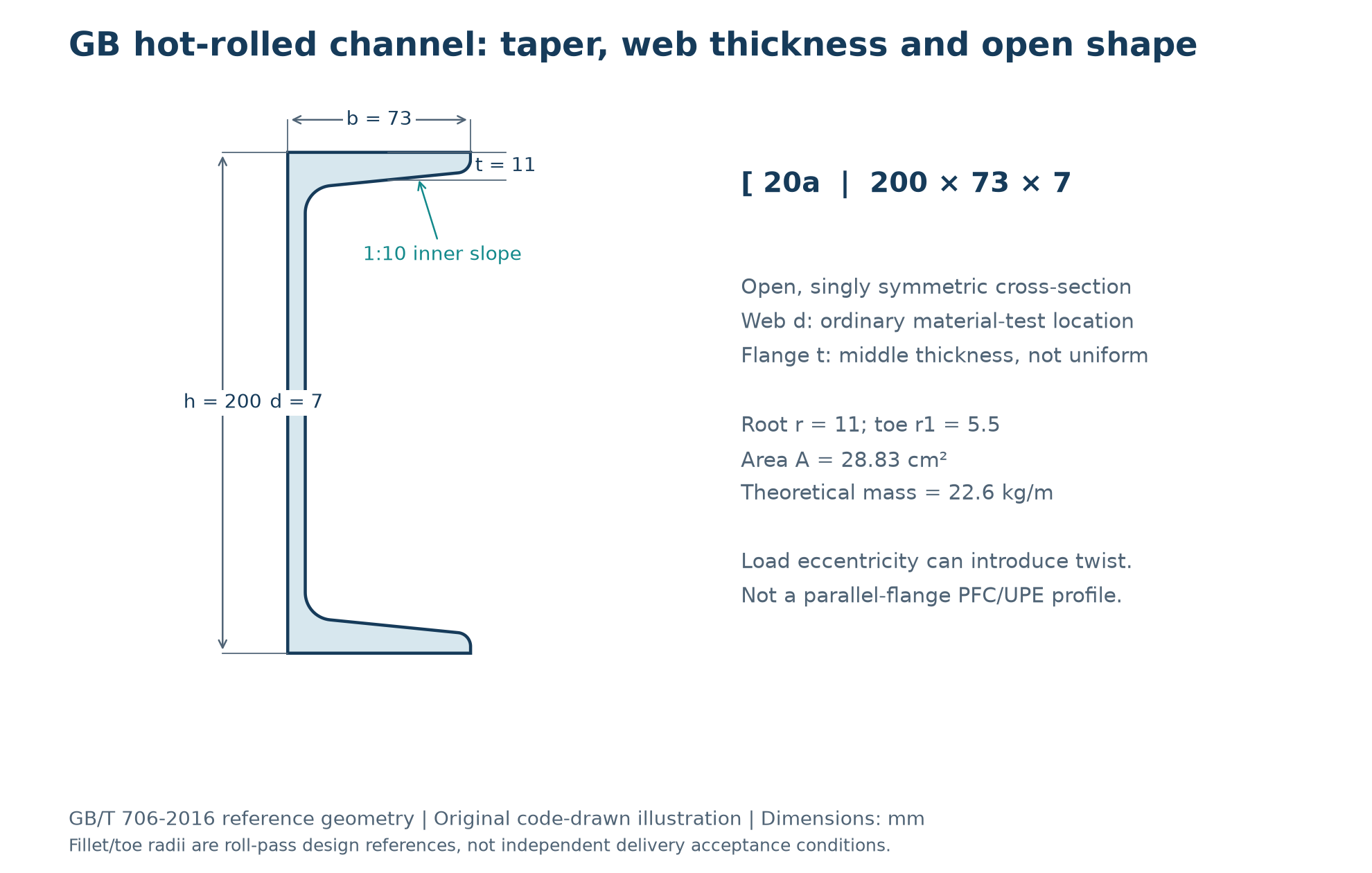
Here h is the overall depth, b the flange width, d the web thickness and t the middle flange thickness. The inside face is tapered; t is not a constant plate thickness. The final column is an ordinary web-sampling yield reference, not a member resistance or a universal flange design value.
| Model | h × b × d | h mm | b mm | d mm | t mm | A cm² | kg/m | Web-band ReH min, MPa |
|---|---|---|---|---|---|---|---|---|
| 5 | 50×37×4.5 | 50 | 37 | 4.5 | 7.0 | 6.925 | 5.44 | 355 |
| 6.3 | 63×40×4.8 | 63 | 40 | 4.8 | 7.5 | 8.446 | 6.63 | 355 |
| 6.5 | 65×40×4.3 | 65 | 40 | 4.3 | 7.5 | 8.292 | 6.51 | 355 |
| 8 | 80×43×5.0 | 80 | 43 | 5.0 | 8.0 | 10.24 | 8.04 | 355 |
| 10 | 100×48×5.3 | 100 | 48 | 5.3 | 8.5 | 12.74 | 10.0 | 355 |
| 12 | 120×53×5.5 | 120 | 53 | 5.5 | 9.0 | 15.36 | 12.1 | 355 |
| 12.6 | 126×53×5.5 | 126 | 53 | 5.5 | 9.0 | 15.69 | 12.3 | 355 |
| 14a | 140×58×6.0 | 140 | 58 | 6.0 | 9.5 | 18.51 | 14.5 | 355 |
| 14b | 140×60×8.0 | 140 | 60 | 8.0 | 9.5 | 21.31 | 16.7 | 355 |
| 16a | 160×63×6.5 | 160 | 63 | 6.5 | 10.0 | 21.95 | 17.2 | 355 |
| 16b | 160×65×8.5 | 160 | 65 | 8.5 | 10.0 | 25.15 | 19.8 | 355 |
| 18a | 180×68×7.0 | 180 | 68 | 7.0 | 10.5 | 25.69 | 20.2 | 355 |
| 18b | 180×70×9.0 | 180 | 70 | 9.0 | 10.5 | 29.29 | 23.0 | 355 |
| 20a | 200×73×7.0 | 200 | 73 | 7.0 | 11.0 | 28.83 | 22.6 | 355 |
| 20b | 200×75×9.0 | 200 | 75 | 9.0 | 11.0 | 32.83 | 25.8 | 355 |
| 22a | 220×77×7.0 | 220 | 77 | 7.0 | 11.5 | 31.83 | 25.0 | 355 |
| 22b | 220×79×9.0 | 220 | 79 | 9.0 | 11.5 | 36.23 | 28.5 | 355 |
| 24a | 240×78×7.0 | 240 | 78 | 7.0 | 12.0 | 34.21 | 26.9 | 355 |
| 24b | 240×80×9.0 | 240 | 80 | 9.0 | 12.0 | 39.01 | 30.6 | 355 |
| 24c | 240×82×11.0 | 240 | 82 | 11.0 | 12.0 | 43.81 | 34.4 | 355 |
| 25a | 250×78×7.0 | 250 | 78 | 7.0 | 12.0 | 34.91 | 27.4 | 355 |
| 25b | 250×80×9.0 | 250 | 80 | 9.0 | 12.0 | 39.91 | 31.3 | 355 |
| 25c | 250×82×11.0 | 250 | 82 | 11.0 | 12.0 | 44.91 | 35.3 | 355 |
| 27a | 270×82×7.5 | 270 | 82 | 7.5 | 12.5 | 39.27 | 30.8 | 355 |
| 27b | 270×84×9.5 | 270 | 84 | 9.5 | 12.5 | 44.67 | 35.1 | 355 |
| 27c | 270×86×11.5 | 270 | 86 | 11.5 | 12.5 | 50.07 | 39.3 | 355 |
| 28a | 280×82×7.5 | 280 | 82 | 7.5 | 12.5 | 40.02 | 31.4 | 355 |
| 28b | 280×84×9.5 | 280 | 84 | 9.5 | 12.5 | 45.62 | 35.8 | 355 |
| 28c | 280×86×11.5 | 280 | 86 | 11.5 | 12.5 | 51.22 | 40.2 | 355 |
| 30a | 300×85×7.5 | 300 | 85 | 7.5 | 13.5 | 43.89 | 34.5 | 355 |
| 30b | 300×87×9.5 | 300 | 87 | 9.5 | 13.5 | 49.89 | 39.2 | 355 |
| 30c | 300×89×11.5 | 300 | 89 | 11.5 | 13.5 | 55.89 | 43.9 | 355 |
| 32a | 320×88×8.0 | 320 | 88 | 8.0 | 14.0 | 48.50 | 38.1 | 355 |
| 32b | 320×90×10.0 | 320 | 90 | 10.0 | 14.0 | 54.90 | 43.1 | 355 |
| 32c | 320×92×12.0 | 320 | 92 | 12.0 | 14.0 | 61.30 | 48.1 | 355 |
| 36a | 360×96×9.0 | 360 | 96 | 9.0 | 16.0 | 60.89 | 47.8 | 355 |
| 36b | 360×98×11.0 | 360 | 98 | 11.0 | 16.0 | 68.09 | 53.5 | 355 |
| 36c | 360×100×13.0 | 360 | 100 | 13.0 | 16.0 | 75.29 | 59.1 | 355 |
| 40a | 400×100×10.5 | 400 | 100 | 10.5 | 18.0 | 75.04 | 58.9 | 355 |
| 40b | 400×102×12.5 | 400 | 102 | 12.5 | 18.0 | 83.04 | 65.2 | 355 |
| 40c | 400×104×14.5 | 400 | 104 | 14.5 | 18.0 | 91.04 | 71.5 | 355 |
Inspection, traceability and enquiry
Check depth, flange width, web and middle-flange thickness, flange inclination, straightness and twist. For paired channels, identify orientation and matching lengths without implying that material acceptance certifies the built-up assembly.
- State the full designation, exact grade/material edition, dimensional edition, lengths and quantity; identify any approved deviation from the normal hot-rolled scope.
- Define the documentary requirement before ordering: heat analysis, applicable tensile results, the impact-test regime where required, and traceability between the certificate and supplied bundles. Do not assume a particular third-party certificate or inspection service.
- Specify theoretical or actual-mass settlement and any special dimensional acceptance before quotation. Extra tests, coatings, fabrication or additional delivery conditions are not implied by a general grade enquiry.
Lead time: a typical mill order is about 35 days. Stocked sizes: 1–3 days, subject to enquiry and confirmation of the individual size, grade, quantity and delivery requirement. A tabulated section is not a statement that it is held in stock.
Related section and material comparisons
For a different rolled geometry in the same material, see Q355B H-beams. The Q355B plate material page is a separate product form: it must not replace the section-specific sampling and shape requirements above.
The parallel-flange channel family overview and S355JR UPE/PFC reference explain a different channel system. They do not turn the tapered GB channel into a PFC or establish equal mass, bolt seating or resistance.
Compare this GB/T 706 tapered channel family in the other grade: Q235B Channels.
Frequently asked questions
Are these Chinese channels UPN, UPE or PFC?
No. They use the GB/T 706 tapered channel series. UPN also has a tapered family but has different standard geometry; UPE/PFC are parallel-flange families. Match the full dimensions, material standard, tolerances and connection before approving any replacement. The family names are not interchangeable stock descriptions.
Why can a channel twist under a vertical load?
A channel is an open, singly symmetric section whose shear centre generally does not coincide with the centroid. If the load does not pass through the appropriate torsion-free load line, twisting can accompany bending. Establish the load entry point, restraint and end conditions in the structural model, including loads from flange-mounted brackets.
Can two channels be treated as one box section?
Only if the engineered arrangement and its connections justify the assumed composite action. Orientation, separation, battens or stitching and end load distribution determine the load path. Merely placing two channels together does not provide the torsional stiffness of a continuously closed section.
Is t the same as the web thickness d?
No. d is the web thickness; t is the middle flange thickness on the tapered inner face. Channel20a has d = 7 mm and t = 11 mm. The ordinary material sample is taken in the web under GB/T 706; flange bearing, bolt seating and local flange design remain separate issues.
Is Q355B simply the new name for every Q345B product?
No. The 2018 material system replaced the older Q345 grade designation, but a historical certificate does not automatically meet every Q355B chemistry, thickness-band and toughness requirement. Compare the original order and actual test results. The hot-rolled route on this page is also distinct from Q355N and Q355M delivery conditions.
Does the 0.035% P/S table exclude all material above it?
Not unconditionally for sections. The hot-rolled Q355B table permits a +0.005 percentage-point allowance for sections and bars, giving 0.040% for each of P and S. If the project requires 0.035% without that allowance, state the tighter contractual requirement. Do not confuse heat maxima with finished-product analysis deviations.
Does Q355B guarantee 34 J in all directions and at low temperature?
No. The reference is 34 J longitudinal at +20 °C when testing applies. A 27 J transverse option requires agreement, and reduced-size specimen rules can change the applicable acceptance values. B quality does not establish subzero toughness. State the required test temperature, orientation, specimen basis and reporting rather than relying on the B suffix alone.
How should a welding and delivery enquiry be written?
Specify the exact section, Q355B to the hot-rolled GB/T 1591-2018 route, the GB/T 706 dimensional edition, length, quantity and test documentation. Include any restricted chemistry, CEV, actual impact test or finished-product analysis requirement. Provide joint details if welding suitability is being assessed. Typical mill orders are about 35 days; stocked sizes are 1–3 days only subject to individual enquiry confirmation.
For an enquiry to Gangsteel, provide the exact section and material specification, rather than a grade name alone. Quote acceptance remains subject to confirmation of the requested size, quantity and test scope.