


Steel Beams
EN 10025-2 S235JR IPE Beams: Sizes & Properties
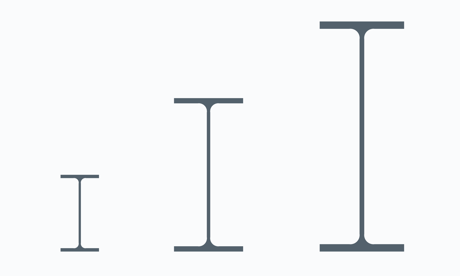
S235JR IPE Beams: Grade and Section in One Order
An S235JR IPE beam is a narrow parallel-flange I-section from EN 10365 rolled in the lowest-strength EN 10025-2 grade with a +20 °C impact quality. Gangsteel supplies this combination for purlins, secondary beams, mezzanine joists, platform framing and other members where stiffness or simple fabrication matters more than strength. Quote it as, for example, “IPE 270, EN 10025-2 S235JR”.
| Item | Value | Note |
|---|---|---|
| Material | EN 10025-2:2019 S235JR (1.0038) | Impact quality 27 J at +20 °C |
| Section series | IPE to EN 10365:2017 | Standard IPE 80–600; IPE A, IPE O and IPE V variants are separate series |
| Tolerances | EN 10034 | Depth, width, thickness, out-of-square, straightness |
| General delivery | EN 10025-1 | Testing, inspection documents, marking |
| Supply | Gangsteel supplies EN 10025-2 S235JR IPE beams | Sizes, quantities and stock confirmed per enquiry |
| Former designation | St 37-2 (DIN 17100, withdrawn) | Historical only |
IPE 80 to IPE 600 in S235JR
| IPE | h mm | b mm | tw mm | tf mm | kg/m | ReH MPa | Wpl,y cm³ | Wpl,y·ReH kNm | Class, axial |
|---|---|---|---|---|---|---|---|---|---|
| IPE 80 | 80.0 | 46.0 | 3.8 | 5.2 | 6.0 | 235 | 23.2 | 5 | Class 1 |
| IPE 100 | 100.0 | 55.0 | 4.1 | 5.7 | 8.1 | 235 | 39.4 | 9 | Class 1 |
| IPE 120 | 120.0 | 64.0 | 4.4 | 6.3 | 10.4 | 235 | 60.7 | 14 | Class 1 |
| IPE 140 | 140.0 | 73.0 | 4.7 | 6.9 | 12.9 | 235 | 88.3 | 21 | Class 1 |
| IPE 160 | 160.0 | 82.0 | 5.0 | 7.4 | 15.8 | 235 | 124 | 29 | Class 1 |
| IPE 180 | 180.0 | 91.0 | 5.3 | 8.0 | 18.8 | 235 | 166 | 39 | Class 1 |
| IPE 200 | 200.0 | 100.0 | 5.6 | 8.5 | 22.4 | 235 | 221 | 52 | Class 1 |
| IPE 220 | 220.0 | 110.0 | 5.9 | 9.2 | 26.2 | 235 | 285 | 67 | Class 1 |
| IPE 240 | 240.0 | 120.0 | 6.2 | 9.8 | 30.7 | 235 | 367 | 86 | Class 1 |
| IPE 270 | 270.0 | 135.0 | 6.6 | 10.2 | 36.1 | 235 | 484 | 114 | Class 2 |
| IPE 300 | 300.0 | 150.0 | 7.1 | 10.7 | 42.2 | 235 | 628 | 148 | Class 2 |
| IPE 330 | 330.0 | 160.0 | 7.5 | 11.5 | 49.1 | 235 | 804 | 189 | Class 2 |
| IPE 360 | 360.0 | 170.0 | 8.0 | 12.7 | 57.1 | 235 | 1,020 | 240 | Class 2 |
| IPE 400 | 400.0 | 180.0 | 8.6 | 13.5 | 66.3 | 235 | 1,310 | 308 | Class 3 |
| IPE 450 | 450.0 | 190.0 | 9.4 | 14.6 | 77.6 | 235 | 1,700 | 400 | Class 3 |
| IPE 500 | 500.0 | 200.0 | 10.2 | 16.0 | 90.7 | 235 | 2,190 | 515 | Class 3 |
| IPE 550 | 550.0 | 210.0 | 11.1 | 17.2 | 106 | 225 | 2,790 | 628 | Class 3 |
| IPE 600 | 600.0 | 220.0 | 12.0 | 19.0 | 122 | 225 | 3,510 | 790 | Class 3 |
Only IPE 550 and IPE 600 have flanges thicker than 16 mm (17.2 mm and 19.0 mm), so in S235JR they are rated at 225 MPa while IPE 80 to IPE 500 are rated at 235 MPa. Because ε = 1.0 for 235 MPa, S235JR gives the most favourable cross-section classes of any grade: in pure compression, 9 of the 18 sizes are Class 1 and the deeper sections move to higher classes only because of their slender webs.
Wpl,y·ReH is the characteristic plastic moment of the cross-section about the major axis, using the S235JR yield band for that flange thickness. It is a cross-section value only: it excludes partial factors, lateral-torsional buckling, shear interaction and serviceability, and is not a safe working load. The class column applies the EN 1993-1-1 width-to-thickness limits for pure axial compression with ε = √(235/ReH); in pure major-axis bending every standard IPE in this grade is Class 1. Confirm classification with the design code and national annex used on the project.
S235JR Chemistry Limits Relevant to IPE
| Element | Limit |
|---|---|
| C | 0.17 |
| Mn | 1.40 |
| Si | no maximum in grade row |
| P | 0.040 |
| S | 0.040 |
| N | 0.012 (waived with total Al ≥ 0.020% or reported N-binding elements) |
| Cu | 0.55 |
| CEV | 0.35 |
Carbon is limited to 0.17% and CEV to 0.35% for every IPE size, since no IPE flange approaches the 40 mm step where these limits change. Silicon has no maximum in the grade row; for hot-dip galvanized members, agree the 0.14–0.25% silicon range with P ≤ 0.035% at order stage.
S235JR Tensile and Impact Requirements
| Property | tf ≤ 16 mm (IPE 80–500) | 16 mm < tf ≤ 40 mm (IPE 550, 600) |
|---|---|---|
| Minimum ReH | 235 MPa | 225 MPa |
| Rm | 360–510 MPa | 360–510 MPa |
| Minimum A (L0 = 5.65√S0) | 26% | 26% |
| Charpy V, minimum | 27 J at +20 °C | 27 J at +20 °C |
IPE 80 and IPE 100 have flanges of only 5.2 mm and 5.7 mm. A full-size 10 × 10 mm Charpy specimen cannot be taken from them, and the EN 10025-1/-2 rules on specimen size and minimum product thickness for impact testing govern. If a +20 °C impact result is needed for these small sizes, agree in the order whether and how it will be reported.
Design Notes Specific to S235JR IPE Members
IPE sections have narrow flanges, so unrestrained beams are frequently governed by lateral-torsional buckling rather than by the plastic moment shown in the table. For long unrestrained spans the advantage of a higher grade is partly lost, which is one reason S235JR remains economical for secondary members with closely spaced restraints or for deflection-governed beams. S235JR IPE 300 has a characteristic plastic moment of about 147 kNm (628 cm³ × 235 MPa); the same section in S355 reaches about 223 kNm, but its buckling resistance rises by a smaller proportion.
S235JR Compared with Other IPE Grades
| Grade | IPE 300 Wpl,y·ReH | Difference that matters |
|---|---|---|
| S235JR | about 147 kNm | Lowest strength, lowest CEV (0.35%) |
| S275JR | about 173 kNm | More resistance; CEV 0.40% |
| S355JR | about 223 kNm | Highest resistance; CEV 0.45%; tighter weld control |
| S235J0 / S235J2 | about 147 kNm | Same strength, colder impact test (0 °C / −20 °C); order by name |
Fabrication: Welding, Cutting and Coating
S235JR IPE beams weld readily; a CEV of 0.35% and flanges below 20 mm mean preheat is rarely needed, though the welding procedure must still follow the applicable fabrication standard. Thin webs of the small sizes are prone to distortion and burn-through, so heat input rather than metallurgy is the usual limit. Drilling, sawing, coping and thermal cutting are straightforward. For galvanizing, specify the silicon option; thin IPE webs and flanges are also sensitive to distortion in the zinc bath, which the galvanizer should know at enquiry.
Delivery Condition, Inspection and Lead Time
| Item | Specify | Reason |
|---|---|---|
| Delivery condition | +AR or +N where required | Not implied by the grade name |
| Impact test | Whether the 27 J at +20 °C result must be reported, and specimen size for thin flanges | Thin IPE flanges limit specimen size |
| Inspection document | EN 10204 3.1 for heat-specific results | Traceability to the delivered pieces |
| Dimensions | EN 10034 tolerances, lengths and cut list | Nominal values are not tolerances |
| Mass basis | Theoretical or weighed | Avoids invoicing disputes |
Lead time: typical delivery is about 35 days for mill orders, and sizes available from stock can ship in 1–3 days. Stock availability is confirmed size by size at enquiry; the IPE table on this page is reference geometry, not a stock list.
RFQ Checklist
- Full designation such as IPE 300, quantity and lengths.
- EN 10025-2 S235JR with delivery condition and any chemistry options.
- Impact verification and EN 10204 document type.
- Processing (cutting, drilling, blasting, priming), packing and destination.
- Whether stock sizes are preferred for 1–3 day dispatch or a mill order is acceptable.
For heavier wide-flange alternatives in the same grade see EN 10025-2 S235JR HEA and HEB beams. The IPE beam size range and grade overview summarises the IPE series across grades, and connection plates are covered by EN 10025-2 S235JR steel plate. The structural steel sections guide compares section families.
The same IPE series in other EN 10025-2 grades: S275JR IPE beams, S355JR IPE beams, S355J2 IPE beams.
Frequently Asked Questions
Which IPE sizes have a reduced yield in S235JR?
Only IPE 550 and IPE 600, whose flanges are 17.2 mm and 19.0 mm thick. They are rated at 225 MPa; IPE 80 to IPE 500 are rated at 235 MPa because their flanges are 16 mm or thinner.
Is S235JR a sensible grade for IPE purlins and secondary beams?
Often yes. Such members are commonly governed by deflection or lateral-torsional buckling, where a higher yield strength gives less benefit. The final choice belongs to the design engineer, based on spans, restraint spacing and loads.
Can impact tests be done on IPE 80 and IPE 100 in S235JR?
Their flanges are 5.2 mm and 5.7 mm thick, too thin for a full-size Charpy specimen. EN 10025 rules on specimen size and minimum thickness apply, so agree in the order whether impact results are required for these sizes and how they will be reported.
How fast can S235JR IPE beams be delivered?
Sizes available from stock can ship in 1 to 3 days; mill orders typically take about 35 days. Stock is confirmed size by size at enquiry, so list the exact IPE designations, lengths and quantities in the RFQ.
Is S235JR IPE suitable for galvanizing?
Yes, if the galvanizing chemistry option is agreed: silicon 0.14 to 0.25% and phosphorus not above 0.035%. Thin sections can distort in the bath, so long slender IPE members should be discussed with the galvanizer.
What is the difference between S235JR IPE and S235JR HEA beams?
The material requirements are the same, but IPE is a narrow-flange beam with flange width about half the depth, while HE A is a wide-flange section with width close to the depth. IPE is efficient in bending about the major axis; HE A has much higher minor-axis stiffness and is often used for columns.
What should the certificate show for S235JR IPE?
EN 10025-2 S235JR, heat number, chemistry with CEV, tensile results, any ordered impact results, the IPE designation and the EN 10204 document type. The heat on the certificate must match the marking on the delivered beams.