


Steel Beams
EN 10025-2 S355J2 IPE Beams: Sizes & Properties
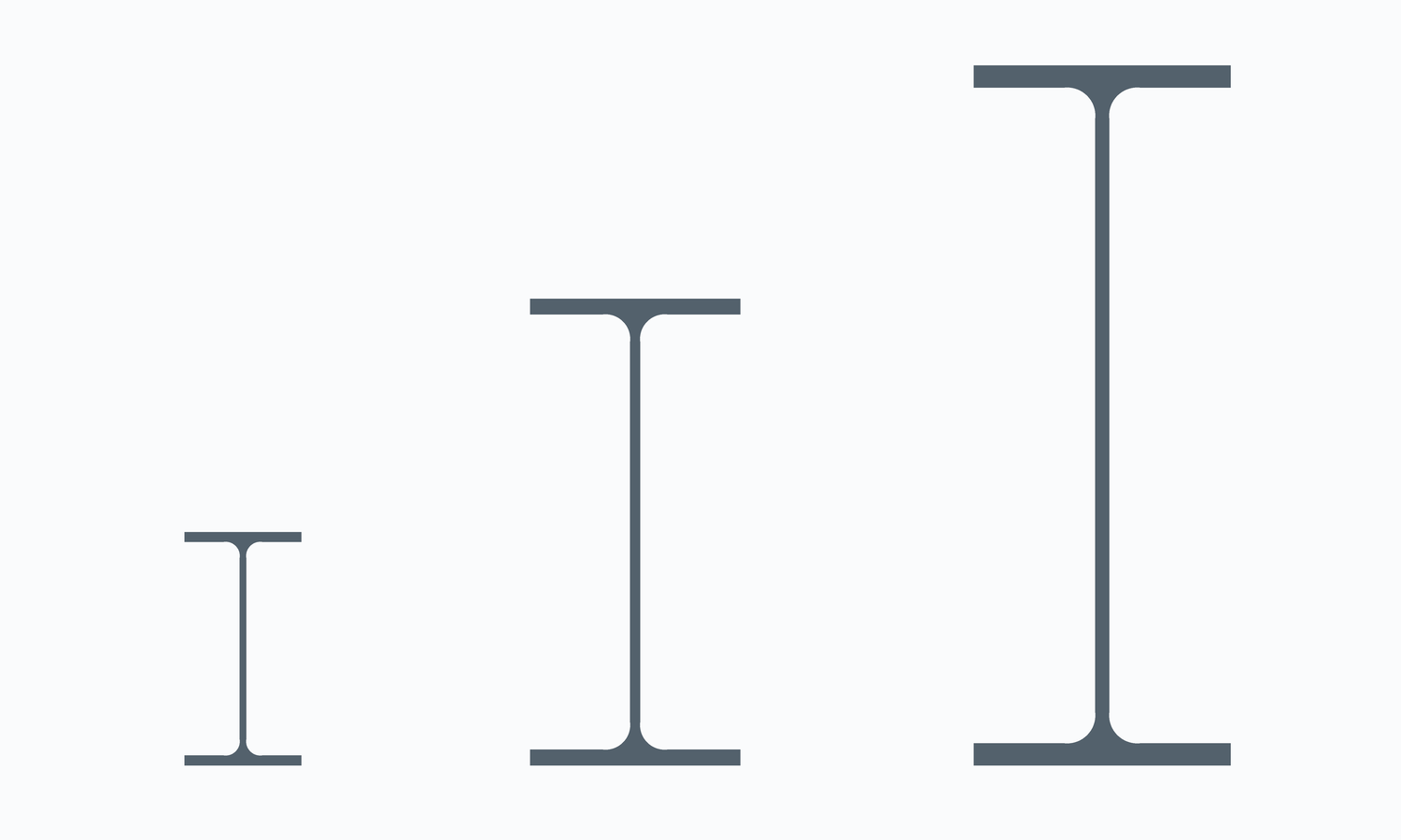
S355J2 IPE Beams: Grade and Section in One Order
S355J2 IPE beams use the 355 MPa EN 10025-2 grade that is impact-tested at −20 °C and made as fully killed steel. They are the usual EN choice for IPE beams in external, unheated, crane-supporting or dynamically loaded structures. Gangsteel supplies S355J2 IPE beams; quote, for example, “IPE 450, EN 10025-2 S355J2” and add +N if a normalized condition is required.
| Item | Value | Note |
|---|---|---|
| Material | EN 10025-2:2019 S355J2 (1.0577) | Impact quality 27 J at −20 °C |
| Section series | IPE to EN 10365:2017 | Standard IPE 80–600; IPE A, IPE O and IPE V variants are separate series |
| Tolerances | EN 10034 | Depth, width, thickness, out-of-square, straightness |
| General delivery | EN 10025-1 | Testing, inspection documents, marking |
| Supply | Gangsteel supplies EN 10025-2 S355J2 IPE beams | Sizes, quantities and stock confirmed per enquiry |
| Former designations | S355J2G3 / S355J2G4; St 52-3 (withdrawn) | Historical only |
| Deoxidation | Fully killed with nitrogen-binding elements | Reported on the certificate |
IPE 80 to IPE 600 in S355J2
| IPE | h mm | b mm | tw mm | tf mm | kg/m | ReH MPa | Wpl,y cm³ | Wpl,y·ReH kNm | Class, axial | Charpy specimen, indicative |
|---|---|---|---|---|---|---|---|---|---|---|
| IPE 80 | 80.0 | 46.0 | 3.8 | 5.2 | 6.0 | 355 | 23.2 | 8 | Class 1 | By agreement |
| IPE 100 | 100.0 | 55.0 | 4.1 | 5.7 | 8.1 | 355 | 39.4 | 14 | Class 1 | 5 mm sub-size |
| IPE 120 | 120.0 | 64.0 | 4.4 | 6.3 | 10.4 | 355 | 60.7 | 22 | Class 1 | 5 mm sub-size |
| IPE 140 | 140.0 | 73.0 | 4.7 | 6.9 | 12.9 | 355 | 88.3 | 31 | Class 1 | 5 mm sub-size |
| IPE 160 | 160.0 | 82.0 | 5.0 | 7.4 | 15.8 | 355 | 124 | 44 | Class 1 | 5 mm sub-size |
| IPE 180 | 180.0 | 91.0 | 5.3 | 8.0 | 18.8 | 355 | 166 | 59 | Class 2 | 7.5 mm sub-size |
| IPE 200 | 200.0 | 100.0 | 5.6 | 8.5 | 22.4 | 355 | 221 | 78 | Class 2 | 7.5 mm sub-size |
| IPE 220 | 220.0 | 110.0 | 5.9 | 9.2 | 26.2 | 355 | 285 | 101 | Class 2 | 7.5 mm sub-size |
| IPE 240 | 240.0 | 120.0 | 6.2 | 9.8 | 30.7 | 355 | 367 | 130 | Class 2 | 7.5 mm sub-size |
| IPE 270 | 270.0 | 135.0 | 6.6 | 10.2 | 36.1 | 355 | 484 | 172 | Class 3 | 7.5 mm sub-size |
| IPE 300 | 300.0 | 150.0 | 7.1 | 10.7 | 42.2 | 355 | 628 | 223 | Class 4 | 7.5 mm sub-size |
| IPE 330 | 330.0 | 160.0 | 7.5 | 11.5 | 49.1 | 355 | 804 | 285 | Class 4 | Full-size |
| IPE 360 | 360.0 | 170.0 | 8.0 | 12.7 | 57.1 | 355 | 1,020 | 362 | Class 4 | Full-size |
| IPE 400 | 400.0 | 180.0 | 8.6 | 13.5 | 66.3 | 355 | 1,310 | 465 | Class 4 | Full-size |
| IPE 450 | 450.0 | 190.0 | 9.4 | 14.6 | 77.6 | 355 | 1,700 | 604 | Class 4 | Full-size |
| IPE 500 | 500.0 | 200.0 | 10.2 | 16.0 | 90.7 | 355 | 2,190 | 777 | Class 4 | Full-size |
| IPE 550 | 550.0 | 210.0 | 11.1 | 17.2 | 106 | 345 | 2,790 | 963 | Class 4 | Full-size |
| IPE 600 | 600.0 | 220.0 | 12.0 | 19.0 | 122 | 345 | 3,510 | 1211 | Class 4 | Full-size |
IPE 80 to IPE 500 are in the 355 MPa band and IPE 550 and IPE 600 in the 345 MPa band. Because no IPE flange exceeds 30 mm, the 0.20% carbon and 0.45% CEV limits apply to every size; the 0.22% carbon and 0.47% CEV steps seen on heavy HE B sections do not occur in the IPE range. In pure compression 5 of 18 sizes are Class 1, as for S355JR.
Wpl,y·ReH is the characteristic plastic moment of the cross-section about the major axis, using the S355J2 yield band for that flange thickness. It is a cross-section value only: it excludes partial factors, lateral-torsional buckling, shear interaction and serviceability, and is not a safe working load. The class column applies the EN 1993-1-1 width-to-thickness limits for pure axial compression with ε = √(235/ReH); in pure major-axis bending every standard IPE in this grade is Class 1. Confirm classification with the design code and national annex used on the project.
S355J2 Chemistry Limits Relevant to IPE
| Element | Limit |
|---|---|
| C | 0.20 |
| Mn | 1.60 |
| Si | 0.55 |
| P | 0.030 |
| S | 0.030 |
| N | no maximum; fully killed with N-binding elements (e.g. Al ≥ 0.02%), reported |
| Cu | 0.55 |
| CEV | 0.45 |
S355J2 limits phosphorus and sulfur to 0.030% each and requires fully killed steel with enough nitrogen-binding elements, typically at least 0.02% aluminium; there is therefore no separate nitrogen maximum. These requirements support toughness in the heat-affected zone of welded connections.
S355J2 Tensile and Impact Requirements
| Property | tf ≤ 16 mm (IPE 80–500) | 16 mm < tf ≤ 40 mm (IPE 550, 600) |
|---|---|---|
| Minimum ReH | 355 MPa | 345 MPa |
| Rm | 470–630 MPa | 470–630 MPa |
| Minimum A (L0 = 5.65√S0) | 22% | 22% |
| Charpy V, minimum | 27 J at −20 °C | 27 J at −20 °C |
The −20 °C, 27 J requirement can only be demonstrated where a valid specimen can be taken. IPE 80 and IPE 100 flanges (5.2 and 5.7 mm) are too thin for full-size specimens, and sizes with flanges under about 11 mm (roughly IPE 120 to IPE 300) generally need sub-size specimens; agree the specimen size and the energy basis in the order. The test temperature is not a service-temperature guarantee.
Design Notes Specific to S355J2 IPE Members
S355J2 IPE is commonly chosen for crane runway beams, external canopies, bridges for pedestrians and plant structures, where low-temperature toughness and fatigue are relevant. The required impact quality for a member depends on its thickness, stress level and detail under the fracture-toughness rules of the design code; for thin IPE flanges J2 is often sufficient, but the engineer decides. Strength values are identical to S355JR, so cross-section resistances in the table match S355JR. The last column is indicative only: it shows the largest Charpy specimen that the nominal flange thickness usually permits (full-size 10 mm, or 7.5 mm and 5 mm sub-size, whose minimum energies are reduced in proportion under EN 10025). The specimen actually used must be stated on the certificate.
S355J2 Compared with Other IPE Grades
| Grade | Key difference | Ordering consequence |
|---|---|---|
| S355JR | Impact at +20 °C; C 0.24%; P and S 0.040% | Not acceptable against a J2 specification |
| S355K2 | Same temperature, 40 J instead of 27 J | A J2 certificate does not prove K2 |
| S355J2+N | Same grade in normalized or normalizing-rolled condition | +N must be ordered |
| ASTM A992 | W shapes under a different standard | Not an IPE grade; see ASTM A992 wide flange W-beams |
Fabrication: Welding, Cutting and Coating
Lower carbon, phosphorus and sulfur than S355JR help weld-zone toughness and cracking resistance. Preheat is governed by CEV, combined thickness, restraint and hydrogen; IPE flanges up to 19 mm rarely need thickness-driven preheat. EN 10025-2 footnotes the galvanizing silicon option to JR grades, so galvanizing chemistry for J2 IPE should be agreed explicitly.
Delivery Condition, Inspection and Lead Time
| Item | Specify | Reason |
|---|---|---|
| Delivery condition | +AR or +N where required | Not implied by the grade name |
| Impact test | Whether the 27 J at −20 °C result must be reported, and specimen size for thin flanges | Thin IPE flanges limit specimen size |
| Inspection document | EN 10204 3.1 for heat-specific results | Traceability to the delivered pieces |
| Dimensions | EN 10034 tolerances, lengths and cut list | Nominal values are not tolerances |
| Mass basis | Theoretical or weighed | Avoids invoicing disputes |
Lead time: typical delivery is about 35 days for mill orders, and sizes available from stock can ship in 1–3 days. Stock availability is confirmed size by size at enquiry; the IPE table on this page is reference geometry, not a stock list.
RFQ Checklist
- Full designation such as IPE 300, quantity and lengths.
- EN 10025-2 S355J2 with delivery condition and any chemistry options.
- Impact verification and EN 10204 document type.
- Processing (cutting, drilling, blasting, priming), packing and destination.
- Whether stock sizes are preferred for 1–3 day dispatch or a mill order is acceptable.
For heavier wide-flange alternatives in the same grade see EN 10025-2 S355J2 HEA and HEB beams. The IPE beam size range and grade overview summarises the IPE series across grades, and connection plates are covered by EN 10025-2 S355J2 steel plate. The structural steel sections guide compares section families.
The same IPE series in other EN 10025-2 grades: S235JR IPE beams, S275JR IPE beams, S355JR IPE beams.
Frequently Asked Questions
Why specify S355J2 rather than S355JR for IPE beams?
For toughness: J2 is impact-tested at minus 20 °C, fully killed and has tighter phosphorus, sulfur and carbon limits. It is usual for external, unheated, fatigue-loaded or crane structures.
Can small IPE sizes be impact tested at minus 20 degrees Celsius?
IPE 80 and IPE 100 are too thin for full-size Charpy specimens, and sizes with flanges under about 11 mm, roughly up to IPE 300, generally need sub-size specimens. Agree specimen size and energy basis in the order so the certificate demonstrates what the project needs.
Do any IPE sizes have the 0.22% carbon limit in S355J2?
No. That limit applies above 30 mm nominal thickness and the thickest IPE flange is 19.0 mm, so all IPE sizes are limited to 0.20% carbon and 0.45% CEV.
Is S355J2 the same as S355K2?
No. Both are tested at minus 20 °C, but K2 requires 40 J and J2 requires 27 J. Order K2 by name if needed.
Can S355J2 IPE be supplied normalized?
Yes, +N can be specified when the project requires it. It must be ordered explicitly, for example S355J2+N.
What is the lead time for S355J2 IPE beams?
Stock sizes can ship in 1 to 3 days, and mill orders typically take about 35 days. Stock is confirmed per size at enquiry.
How should S355J2 IPE be checked on delivery?
Check the certificate for EN 10025-2 S355J2, delivery condition, heat number, chemistry with CEV, deoxidation and N-binding elements, tensile results and minus 20 °C impact results with specimen size, plus IPE designation and EN 10204 type; then check dimensions to EN 10034.