


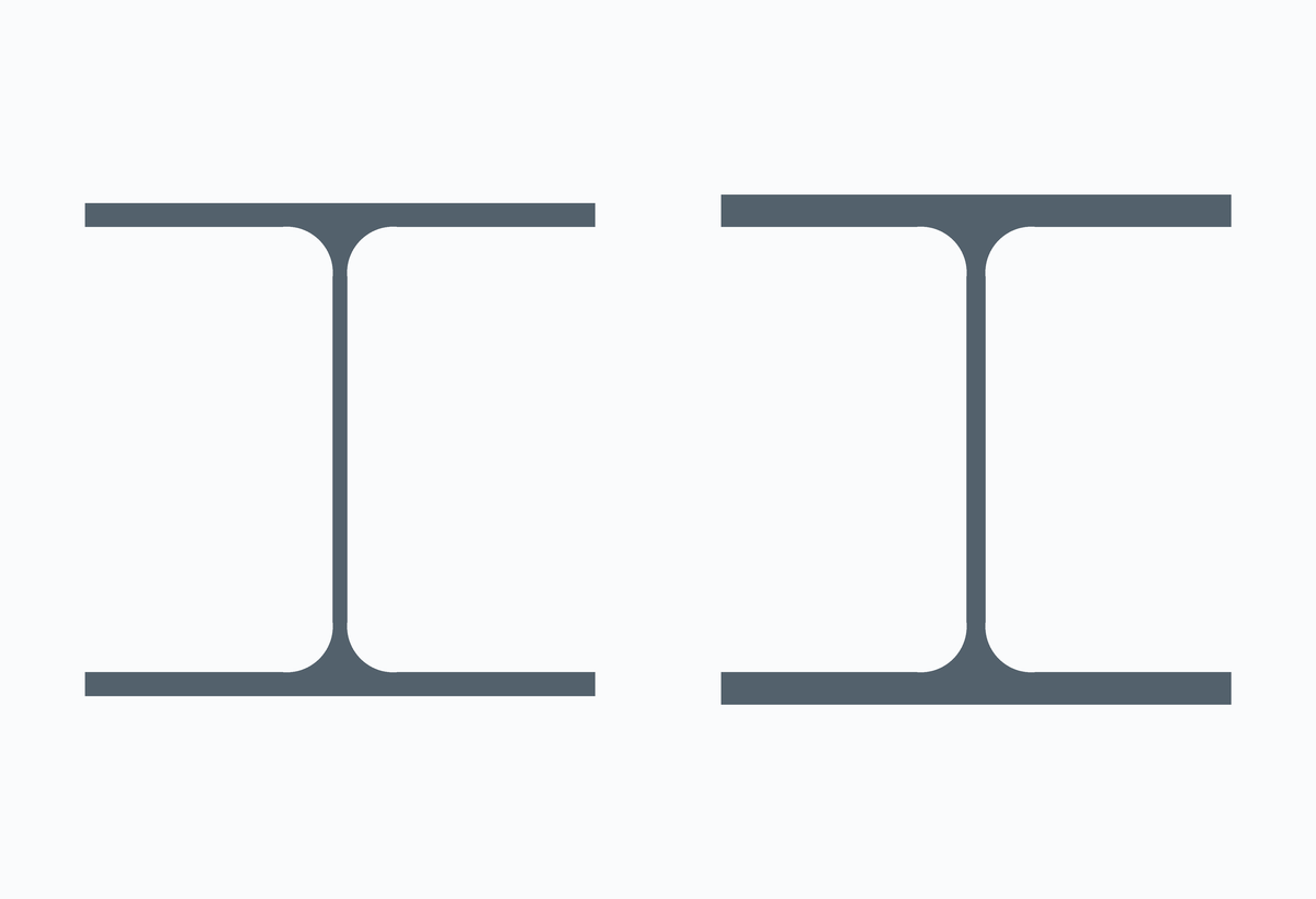
What an S355J2 HE Beam Order Specifies
S355J2 HE beams combine HE A or HE B geometry with the 355 MPa EN 10025-2 grade that is impact-tested at −20 °C and made as fully killed steel. It is the usual EN grade where heavy sections are used in external, unheated or dynamically loaded structures. Enquiries to Gangsteel should state the exact HE designation, EN 10025-2 S355J2 and any delivery condition such as +N.
On this grade three limits change with flange thickness within the HE range: yield strength at 16 mm, and both carbon and CEV at 30 mm. The tables below show which HE sizes fall on each side of those steps.
| Item | Value for this product | Comment |
|---|---|---|
| Material standard | EN 10025-2:2019 | Non-alloy structural steel, hot-rolled products |
| Steel name / number | S355J2 / 1.0577 | Quality J2: impact test temperature in the table below |
| Section series and dimensions | HE A and HE B to EN 10365:2017 | Geometry and nominal mass only; no strength content |
| Shape and dimensional tolerances | EN 10034 | Acceptance of depth, width, thickness, squareness and straightness |
| General delivery requirements | EN 10025-1 | Testing, inspection documents and marking rules shared by the EN 10025 parts |
| Former designations | S355J2G3 / S355J2G4 (EN 10025:1993); St 52-3 (DIN 17100, withdrawn) | The G3/G4 suffixes described delivery practice and are no longer part of the name |
| Deoxidation | Fully killed with nitrogen-binding elements | Reported on the inspection document |
HE A and HE B Sizes Read Through the S355J2 Thickness Bands
EN 10365 fixes the geometry; EN 10025-2 fixes how strong the material must be at a given product thickness. For sections, tensile test pieces are normally taken from the flange, so the flange thickness tf is the practical reference for choosing the applicable S355J2 band. The tables combine both: nominal HE A or HE B dimensions on the left, and on the right the minimum upper yield strength that the S355J2 table requires at that flange thickness. The rows are reference geometry, not a stock list.
| Section | h mm | b mm | tw mm | tf mm | kg/m | Min. ReH MPa | C max % | CEV max % |
|---|---|---|---|---|---|---|---|---|
| HE 100 A | 96 | 100 | 5 | 8 | 16.7 | 355 | 0.20 | 0.45 |
| HE 120 A | 114 | 120 | 5 | 8 | 19.9 | 355 | 0.20 | 0.45 |
| HE 140 A | 133 | 140 | 5.5 | 8.5 | 24.7 | 355 | 0.20 | 0.45 |
| HE 160 A | 152 | 160 | 6 | 9 | 30.4 | 355 | 0.20 | 0.45 |
| HE 180 A | 171 | 180 | 6 | 9.5 | 35.5 | 355 | 0.20 | 0.45 |
| HE 200 A | 190 | 200 | 6.5 | 10 | 42.3 | 355 | 0.20 | 0.45 |
| HE 220 A | 210 | 220 | 7 | 11 | 50.5 | 355 | 0.20 | 0.45 |
| HE 240 A | 230 | 240 | 7.5 | 12 | 60.3 | 355 | 0.20 | 0.45 |
| HE 260 A | 250 | 260 | 7.5 | 12.5 | 68.2 | 355 | 0.20 | 0.45 |
| HE 280 A | 270 | 280 | 8 | 13 | 76.4 | 355 | 0.20 | 0.45 |
| HE 300 A | 290 | 300 | 8.5 | 14 | 88.3 | 355 | 0.20 | 0.45 |
| HE 320 A | 310 | 300 | 9 | 15.5 | 97.6 | 355 | 0.20 | 0.45 |
| HE 340 A | 330 | 300 | 9.5 | 16.5 | 105 | 345 | 0.20 | 0.45 |
| HE 360 A | 350 | 300 | 10 | 17.5 | 112 | 345 | 0.20 | 0.45 |
| HE 400 A | 390 | 300 | 11 | 19 | 125 | 345 | 0.20 | 0.45 |
| HE 450 A | 440 | 300 | 11.5 | 21 | 140 | 345 | 0.20 | 0.45 |
| HE 500 A | 490 | 300 | 12 | 23 | 155 | 345 | 0.20 | 0.45 |
| HE 550 A | 540 | 300 | 12.5 | 24 | 166 | 345 | 0.20 | 0.45 |
| HE 600 A | 590 | 300 | 13 | 25 | 178 | 345 | 0.20 | 0.45 |
| HE 650 A | 640 | 300 | 13.5 | 26 | 190 | 345 | 0.20 | 0.45 |
| HE 700 A | 690 | 300 | 14.5 | 27 | 204 | 345 | 0.20 | 0.45 |
| HE 800 A | 790 | 300 | 15 | 28 | 224 | 345 | 0.20 | 0.45 |
| HE 900 A | 890 | 300 | 16 | 30 | 252 | 345 | 0.20 | 0.45 |
| HE 1000 A | 990 | 300 | 16.5 | 31 | 272 | 345 | 0.22 | 0.47 |
| Section | h mm | b mm | tw mm | tf mm | kg/m | Min. ReH MPa | C max % | CEV max % |
|---|---|---|---|---|---|---|---|---|
| HE 100 B | 100 | 100 | 6 | 10 | 20.4 | 355 | 0.20 | 0.45 |
| HE 120 B | 120 | 120 | 6.5 | 11 | 26.7 | 355 | 0.20 | 0.45 |
| HE 140 B | 140 | 140 | 7 | 12 | 33.7 | 355 | 0.20 | 0.45 |
| HE 160 B | 160 | 160 | 8 | 13 | 42.6 | 355 | 0.20 | 0.45 |
| HE 180 B | 180 | 180 | 8.5 | 14 | 51.2 | 355 | 0.20 | 0.45 |
| HE 200 B | 200 | 200 | 9 | 15 | 61.3 | 355 | 0.20 | 0.45 |
| HE 220 B | 220 | 220 | 9.5 | 16 | 71.5 | 355 | 0.20 | 0.45 |
| HE 240 B | 240 | 240 | 10 | 17 | 83.2 | 345 | 0.20 | 0.45 |
| HE 260 B | 260 | 260 | 10 | 17.5 | 93.0 | 345 | 0.20 | 0.45 |
| HE 280 B | 280 | 280 | 10.5 | 18 | 103 | 345 | 0.20 | 0.45 |
| HE 300 B | 300 | 300 | 11 | 19 | 117 | 345 | 0.20 | 0.45 |
| HE 320 B | 320 | 300 | 11.5 | 20.5 | 127 | 345 | 0.20 | 0.45 |
| HE 340 B | 340 | 300 | 12 | 21.5 | 134 | 345 | 0.20 | 0.45 |
| HE 360 B | 360 | 300 | 12.5 | 22.5 | 142 | 345 | 0.20 | 0.45 |
| HE 400 B | 400 | 300 | 13.5 | 24 | 155 | 345 | 0.20 | 0.45 |
| HE 450 B | 450 | 300 | 14 | 26 | 171 | 345 | 0.20 | 0.45 |
| HE 500 B | 500 | 300 | 14.5 | 28 | 187 | 345 | 0.20 | 0.45 |
| HE 550 B | 550 | 300 | 15 | 29 | 199 | 345 | 0.20 | 0.45 |
| HE 600 B | 600 | 300 | 15.5 | 30 | 212 | 345 | 0.20 | 0.45 |
| HE 650 B | 650 | 300 | 16 | 31 | 225 | 345 | 0.22 | 0.47 |
| HE 700 B | 700 | 300 | 17 | 32 | 241 | 345 | 0.22 | 0.47 |
| HE 800 B | 800 | 300 | 17.5 | 33 | 262 | 345 | 0.22 | 0.47 |
| HE 900 B | 900 | 300 | 18.5 | 35 | 291 | 345 | 0.22 | 0.47 |
| HE 1000 B | 1000 | 300 | 19 | 36 | 314 | 345 | 0.22 | 0.47 |
h is overall depth, b flange width, tw web thickness and tf flange thickness; kg/m is nominal mass. HE A is the lighter series for the same serial size and HE B the heavier one: HE 300 A is 290 mm deep with a 14 mm flange, while HE 300 B is 300 mm deep with a 19 mm flange. Order the full designation, because a drawing note such as “H300” does not distinguish them.
Yield is 355 MPa up to HE 320 A and HE 220 B, and 345 MPa above. Carbon is limited to 0.20% for flanges up to 30 mm and 0.22% above, and CEV rises from 0.45% to 0.47% at the same point. In the listed series, HE 1000 A and HE 650 B to HE 1000 B carry the 0.22% carbon and 0.47% CEV limits.
S355J2 Chemical Composition for HE Sections
| Element | Maximum | How it applies to HE A / HE B |
|---|---|---|
| C | 0.20 / 0.22 | 0.20 up to 30 mm; 0.22 above 30 mm nominal thickness |
| Si | 0.55 | — |
| Mn | 1.60 | — |
| P | 0.030 | Tighter than the JR and J0 qualities |
| S | 0.030 | Tighter than the JR and J0 qualities |
| N | No maximum listed | Fully killed steel; sufficient nitrogen-binding elements (for example Al ≥ 0.02%) are required and reported |
| Cu | 0.55 | — |
| CEV | 0.45 / 0.47 | 0.45 up to 30 mm; 0.47 for 30 mm < t ≤ 40 mm |
S355J2 differs from S355JR mainly in steelmaking quality: phosphorus and sulfur are each limited to 0.030% instead of 0.040%, the steel must be fully killed with enough nitrogen-binding elements (for example at least 0.02% aluminium), and the carbon maximum is lower. There is no separate nitrogen maximum because nitrogen is required to be bound.
CEV = C + Mn/6 + (Cr + Mo + V)/5 + (Cu + Ni)/15, using heat-analysis values. Additional elements, if added, must be stated on the inspection document. These are limits for acceptance, not the composition of any particular heat.
S355J2 Mechanical Properties by Flange Thickness
| Property | tf ≤ 16 mm | 16 mm < tf ≤ 40 mm |
|---|---|---|
| Minimum upper yield strength ReH | 355 MPa | 345 MPa |
| Tensile strength Rm | 470–630 MPa | 470–630 MPa |
| Minimum elongation A, L0 = 5.65√S0 | 22% | 22% |
| Charpy V-notch, minimum | 27 J at −20 °C | 27 J at −20 °C |
The −20 °C, 27 J impact requirement is what makes J2 the common choice for exposed structures. It is a test temperature, not a minimum service temperature: the required toughness for a member depends on thickness, stress level, detail category and the code used, for example the fracture-toughness provisions of the structural design standard.
How S355J2 Differs from Neighbouring EN 10025-2 Grades
| Grade | Key difference from S355J2 | Ordering consequence |
|---|---|---|
| S355JR / S355J0 | Impact at +20 °C / 0 °C; P and S 0.040% / 0.035%; JR carbon up to 0.24% | Not acceptable against a J2 specification |
| S355K2 | Same −20 °C temperature, but 40 J instead of 27 J | A J2 certificate does not prove the K2 energy |
| S355J2+N | Same grade ordered in the normalized or normalizing-rolled condition | +N must be specified; it is not implied by J2 |
| ASTM A992 | Different standard system; yield range and Fy/Fu limit | Not an equivalence; see ASTM A992 wide flange W-beams if A992 is specified |
When a design requires both a low-temperature impact quality and a guaranteed delivery condition, both must be written into the order, for example S355J2+N.
Welding, Cutting and Galvanizing Notes
S355J2 has the same CEV ceiling as S355JR but lower carbon, phosphorus and sulfur, which helps heat-affected-zone toughness and resistance to solidification cracking. Preheat requirements still depend on CEV, flange thickness, restraint and hydrogen control; thick HE B flanges at 31–36 mm usually need more care than thin HE A flanges. The galvanizing silicon option in EN 10025-2 is footnoted to the JR grades, so galvanizing requirements for J2 material should be agreed explicitly.
Delivery Condition, Heat Treatment and Inspection
| Item | What to specify | Why it matters |
|---|---|---|
| Delivery condition | As-rolled (+AR) or normalized / normalizing rolled (+N) where the order requires it | The grade name alone does not fix the delivery condition; +N must be ordered explicitly |
| Heat treatment after delivery | Normally none for rolled HE beams; any hot forming or stress relief needs an agreed procedure | Uncontrolled heating can alter the certified properties |
| Impact verification | State whether the 27 J at −20 °C test is to be verified and reported | Avoids a certificate that lists the grade but no Charpy result |
| Inspection document | EN 10204 type, typically 3.1 when specific test results are required | Results must be traceable to the heat and the delivered pieces |
| Dimensional acceptance | EN 10034 tolerances, length tolerance and cut-length list | Nominal table values are not tolerance limits |
Ask for the impact results at −20 °C on an EN 10204 3.1 certificate, and check that the stated deoxidation and nitrogen-binding elements are reported.
RFQ Checklist for S355J2 HEA and HEB Beams
- Full section designation, for example HE 300 B, not “H300”.
- Material as EN 10025-2 S355J2, with delivery condition and any options such as galvanizing chemistry.
- Lengths, quantities and total mass basis (theoretical or weighed).
- Impact verification, EN 10204 document type and heat traceability.
- Cutting, drilling, blasting or coating drawings, packing and destination.
Typical lead time is about 35 days for mill orders; sizes available from stock can ship in 1-3 days. Stock availability by size is confirmed at enquiry; the tables on this page are reference geometry, not a stock list.
For flat components in the same structure, order EN 10025-2 S355J2 steel plate separately; plate and section certificates are issued per product. For the narrow-flange alternative see the EN 10365 IPE beam range with EN 10025-2 grades, and for heavier column sections the universal column (UC) range. The structural steel sections selection guide compares the families.
Other EN 10025-2 grades in the same HE A / HE B series: S235JR HEA and HEB beams, S275JR HEA and HEB beams, S355JR HEA and HEB beams.
Frequently Asked Questions
Why is S355J2 specified instead of S355JR for HE beams?
Mainly for toughness: J2 is impact-tested at minus 20 °C, while JR is tested at +20 °C. J2 is also fully killed and has tighter phosphorus, sulfur and carbon limits. Designers choose it for exposed, unheated or fatigue-loaded structures.
Which HEB sizes have the 0.22% carbon limit in S355J2?
Sizes with flanges over 30 mm: HE 650 B to HE 1000 B in the B series, plus HE 1000 A. Smaller sizes are limited to 0.20% carbon. The CEV limit rises from 0.45% to 0.47% at the same thickness.
Does S355J2 guarantee use down to minus 20 degrees Celsius?
No. Minus 20 °C is the Charpy test temperature for the 27 J requirement. Whether a member is suitable at a given service temperature depends on thickness, stress and detailing under the design code. The engineer determines the required quality.
What happened to S355J2G3?
The G3 and G4 suffixes of the older EN 10025 edition described delivery and deoxidation practice. In EN 10025-2 the grade is S355J2, and a required delivery condition is ordered separately, for example S355J2+N.
Is S355J2 the same as S355K2?
No. Both are tested at minus 20 °C, but K2 requires 40 J where J2 requires 27 J. A J2 certificate cannot be used as evidence of K2 energy.
Can S355J2 HE beams be supplied normalized?
A normalized or normalizing-rolled condition (+N) can be specified where the project requires it. It must be stated in the order; S355J2 alone does not imply it.
How should S355J2 HE beams be checked on receipt?
Compare the certificate with the order: EN 10025-2 S355J2, delivery condition, heat number, chemistry including CEV, tensile results, Charpy results at minus 20 °C, section designation and EN 10204 document type. Then check dimensions against EN 10034 and the identification on each piece.