


SS400 Japanese I-beams are tapered-flange rolled I-sections, not smaller H-beams with a different trade name. Material acceptance comes from JIS G 3101; the I-section reference series comes from JIS G 3192. The sloping inner flange affects bolt seating and clear root space even when a comparison beam has the same depth. A designation must therefore retain flange width, web thickness and flange reference thickness.
The standard series below contains 20 rows, from 100 × 75 × 5 × 8 through 600 × 190 × 16 × 35. These are dimensional references rather than an offer that each section can be supplied in SS400 at any quantity. The steel name gives a 400–510 MPa tensile range, while yield depends on the material thickness at the test-piece location. Neither overall depth nor an assumed 400 MPa yield is the correct acceptance basis.
| Order field | Defined scope |
|---|---|
| Product | hot-rolled tapered-flange I-sections |
| Material | JIS G 3101:2024 SS400, rolled steels for general structure |
| Dimensions/product form | JIS G 3192:2024, hot-rolled sections: shape, dimensions, mass, appearance and permitted variations |
| Sampling/testing | JIS G 0416 sample location/preparation; relevant JIS tensile/bend test methods |
| Delivery/document | Hot-rolled section; actual condition and inspection-document requirements identified on the order |
Edition check: the JSA catalogue lists JIS G 3101:2024, issued 20 February 2024, and JIS G 3192:2024, issued 20 November 2024, as valid. This page uses those editions rather than an assumed 2026 revision. The contract must name the applicable material and dimensional editions; a current title does not justify silently mixing old and new radius or mass data.
Section selection and connection engineering
Locate the flange gauge correctly
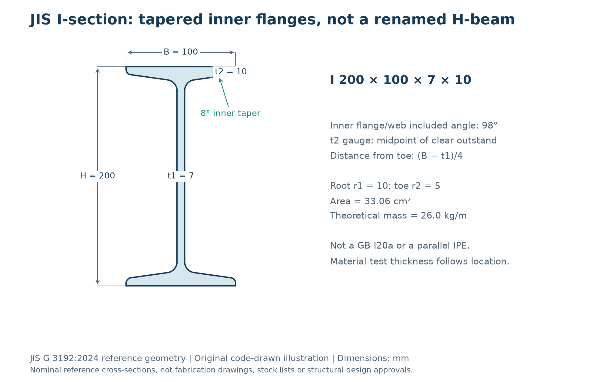
For the JIS I shape, t2 is the thickness at the midpoint of the clear flange outstand: a distance (B−t1)/4 inward from the toe. It is not simply B/4 without allowing for the web. The reference included inner flange/web angle is 98°, equivalent to an 8° incline from horizontal. Those are JIS geometry details; the GB tapered-I slope must not be transferred to this drawing.
Specify a bearing seat that suits the taper
The inner flange is not a parallel mounting face. A flat washer, cleat or end-plate component may not bear as intended if a connection originally designed for IPE or H is copied unchanged. Establish the required tapered washer or shaped seating arrangement through the connection design. The root and toe radii also reduce the flat area available for bolts and prevent a simple outside-width measurement from defining usable clearance.
Do not use the web automatically as the JIS thickness selector
Material thickness is taken at the actual tensile-test location under JIS G 0416. Where the specimen is from the flange, t2 is the relevant reference; the thinner t1 web does not automatically keep a thick-flange section in the 245 MPa band. The largest listed I shape has a 35 mm flange, so a flange-based result belongs to the 235 MPa band. Do not import GB/T 706 web-sampling practice into the JIS order.
Assess weak-axis response and lateral restraint
A vertical load near the web can still produce a beam sensitive to compression-flange instability. Check lateral-torsional buckling, restraint spacing, the load application height and weak-axis bending from eccentric details. A thicker flange variant or an alternative at the same nominal depth can change torsional and minor-axis response. Use the actual section properties and end conditions, not only an area or mass comparison.
Use a complete example rather than a depth shorthand
I 200 × 100 × 7 × 10 has root/toe radii 10/5 mm, area 33.06 cm² and 26.0 kg/m on the reference table. A nominal 6 m piece is 156.0 kg before tolerances. It is not GB I 20a and not IPE 200. An enquiry saying only “SS400 200 mm I-beam” leaves enough ambiguity to change fit, weight and structural resistance.
Material chemistry: heat analysis is not a universal alloy recipe
| Element | Heat-analysis requirement, mass % | Interpretation |
|---|---|---|
| C | No tabulated maximum | No grade-wide carbon cap may be inferred. |
| Si | No tabulated maximum | No SS400 silicon maximum is supplied by the material table. |
| Mn | No tabulated maximum | Do not import another grade’s manganese range. |
| P | 0.050 maximum | Heat-analysis limit, not a typical value. |
| S | 0.050 maximum | Heat-analysis limit, not a typical value. |
An absent limit does not mean zero content or a guaranteed “low-carbon” composition. Elements shown as dashes and unlisted alloying elements may be added as necessary; applicable additions are to be reported. Actual heat results are the input for welding or coating assessment. SS400 has no tabulated carbon-equivalent ceiling, so a Q235B, S235JR or SS540 chemistry/CEV table must not be copied onto this grade.
Keep a heat/ladle analysis distinct from an analysis of a sample cut from the finished section. The figures above are heat-analysis requirements; they are not a separately tabulated finished-product deviation schedule. The compiled material data do not provide numerical product-analysis deviations. If a supplementary product analysis is required, agree the sampling, test method and permitted-deviation/acceptance basis explicitly. Do not borrow GB/T 222 or invent a blanket percentage allowance for a JIS order.
Yield, elongation, bending and toughness
| t, mm | Minimum yield/proof stress, MPa | Tensile strength, MPa |
|---|---|---|
| t ≤16 | 245 | 400–510 |
| 16 <t ≤40 | 235 | 400–510 |
One N/mm² equals one MPa. Unless specified otherwise, yield is the upper yield point ReH; where no yield point appears, the 0.2% proof stress Rp0.2 is determined. The material’s thickness band is not selected by the overall depth or leg width. Sampling and specimen preparation follow JIS G 0416 and the order. The ordinary-section table below is also subject to the small-section provisions; the grade name alone does not select an elongation value.
| t, mm | Tensile test piece | Minimum elongation, % |
|---|---|---|
| t ≤5 | No. 5 | 21 |
| 5 <t ≤16 | No. 1A | 17 |
| 16 <t ≤40 | No. 1A | 21 |
The I-series reaches 35 mm nominal flange thickness. It does not use the >40 mm yield bands on a flange-thickness reference; a 600 mm-deep beam is not 600 mm-thick material.
Small-section qualification: JIS G 3101 requires Annex JA for sections with leg length below 40 mm and permits that route within its 40 to under 70 mm section-leg scope. The applicable section dimension, mechanical route and specimen must be identified on the order/certificate; do not assume every small section uses the ordinary Table 3 elongation rows. Use the Annex JA specimen requirements for the ordered edition; the ordinary Table 3 elongation values above must not be used as a substitute.
| Item | Requirement or limitation |
|---|---|
| Bendability | 180° bend; inside radius 1.5t; No. 1 test piece (No. 3 may be used at thickness≤5 mm). |
| Actual bend test | May be omitted unless required by the purchaser; material still has to meet bendability. |
| Charpy impact | No mandatory SS400 temperature or absorbed-energy value in JIS G 3101. |
| Welding assessment | No automatic CEV limit or no-preheat guarantee; use actual heat chemistry and an appropriate procedure. |
A missing mandatory Charpy requirement is not a statement that the steel has no toughness; it means the grade alone does not qualify a specified impact performance. If low-temperature or other demonstrated toughness is needed, write the test regime into the order or select an approved material quality that specifies it. Any dual certification must satisfy every requirement of both named specifications, not merely a similar tensile range.
JIS G 3192:2024 reference dimensions and theoretical mass
All section dimensions and radii below are millimetres. Area is cm² and theoretical mass is kg/m. The numerical basis is JIS G 3192:2024; do not relabel older catalogue geometry as the current table. Published representative sizes do not establish size/grade availability, rolling frequency or stock. Any other section dimensions require the applicable agreement; no additional sizes have been invented here.
H is depth, B flange width, t1 web thickness and t2 the reference thickness on the tapered flange. r1 is the root radius and r2 the toe radius. The t2 gauge is measured across the clear outstand, as shown in the original diagram; it is not the thinner toe. Use the table for identification and the contractual standard for tolerances and inspection.
| Designation | H (mm) | B (mm) | t1 (mm) | t2 (mm) | r1 (mm) | r2 (mm) | A (cm²) | Mass (kg/m) |
|---|---|---|---|---|---|---|---|---|
| I-100 × 75 × 5 × 8 | 100 | 75 | 5 | 8 | 7 | 3.5 | 16.43 | 12.9 |
| I-125 × 75 × 5.5 × 9.5 | 125 | 75 | 5.5 | 9.5 | 9 | 4.5 | 20.45 | 16.1 |
| I-150 × 75 × 5.5 × 9.5 | 150 | 75 | 5.5 | 9.5 | 9 | 4.5 | 21.83 | 17.1 |
| I-150 × 125 × 8.5 × 14 | 150 | 125 | 8.5 | 14 | 13 | 6.5 | 46.15 | 36.2 |
| I-180 × 100 × 6 × 10 | 180 | 100 | 6 | 10 | 10 | 5 | 30.06 | 23.6 |
| I-200 × 100 × 7 × 10 | 200 | 100 | 7 | 10 | 10 | 5 | 33.06 | 26.0 |
| I-200 × 150 × 9 × 16 | 200 | 150 | 9 | 16 | 15 | 7.5 | 64.16 | 50.4 |
| I-250 × 125 × 7.5 × 12.5 | 250 | 125 | 7.5 | 12.5 | 12 | 6 | 48.79 | 38.3 |
| I-250 × 125 × 10 × 19 | 250 | 125 | 10 | 19 | 21 | 10.5 | 70.73 | 55.5 |
| I-300 × 150 × 8 × 13 | 300 | 150 | 8 | 13 | 12 | 6 | 61.58 | 48.3 |
| I-300 × 150 × 10 × 18.5 | 300 | 150 | 10 | 18.5 | 19 | 9.5 | 83.47 | 65.5 |
| I-300 × 150 × 11.5 × 22 | 300 | 150 | 11.5 | 22 | 23 | 11.5 | 97.88 | 76.8 |
| I-350 × 150 × 9 × 15 | 350 | 150 | 9 | 15 | 13 | 6.5 | 74.58 | 58.5 |
| I-350 × 150 × 12 × 24 | 350 | 150 | 12 | 24 | 25 | 12.5 | 111.1 | 87.2 |
| I-400 × 150 × 10 × 18 | 400 | 150 | 10 | 18 | 17 | 8.5 | 91.73 | 72.0 |
| I-400 × 150 × 12.5 × 25 | 400 | 150 | 12.5 | 25 | 27 | 13.5 | 122.1 | 95.8 |
| I-450 × 175 × 11 × 20 | 450 | 175 | 11 | 20 | 19 | 9.5 | 116.8 | 91.7 |
| I-450 × 175 × 13 × 26 | 450 | 175 | 13 | 26 | 27 | 13.5 | 146.1 | 115 |
| I-600 × 190 × 13 × 25 | 600 | 190 | 13 | 25 | 25 | 12.5 | 169.4 | 133 |
| I-600 × 190 × 16 × 35 | 600 | 190 | 16 | 35 | 38 | 19 | 224.5 | 176 |
Dimensional, shape and mass acceptance belongs to the ordered JIS G 3192 edition. Check depth/leg widths, thicknesses, straightness, twist and squareness or flange alignment as applicable, including the actual root/clearance where a connection depends on it. Agreement on theoretical versus actual-mass settlement is separate from the material tensile result. Catalogue rounding is not a dimensional tolerance.
Inspection documents, traceability and enquiry
The material standard’s 2024 inspection-document default, unless otherwise specified at order, is a JIS G 0415 inspection certificate 3.1. This describes the standard’s documentary requirement, not a claim that a particular independent inspection service or third-party approval is included. State any different or additional document requirement before quotation. The document must identify the actual rolled product, grade, heat/batch and applicable tests; an SS400 plate or bar certificate alone does not identify a supplied section.
- Specify the full section designation, SS400 material edition, dimensional edition, lengths and quantity. Mark special/non-general-purpose rows and any agreed departure from representative sizes.
- State the tensile specimen and applicable mechanical route where critical, including Annex JA for qualifying small sections. Actual bend or supplementary impact tests must be requested when required; do not infer test results from a grade suffix that does not exist.
- Keep heat analysis, any agreed finished-product analysis and dimensional inspection separately traceable. Include restricted chemistry, weld or coating requirements for review without assuming machining, coating, cutting or additional testing services are included.
- Confirm the commercial mass basis, delivery requirements and certificate traceability before release. The reference size tables are not a mill programme or an inventory listing.
Lead time: a typical new mill order is about 35 days. Stocked sizes:1–3 days, subject to enquiry and confirmation of the specific section, grade, quantity and delivery requirement. No table row is represented as immediately available stock.
Related products: comparison is not equivalence
The SS400 plate material page concerns a different product form; it does not replace the section’s sampling, shape or certificate identification. Its legacy catalogue text is not used as the numerical authority for the section tables above.
For a different standard system, see the S235JR IPE reference. A similar strength class is not an automatic replacement: material chemistry, toughness, sampling and the rolled shape must each meet the project specification.
The Q235B i-beams page is another material/shape comparison, not a dual-certification claim. Do not transfer GB dimensional or test-location rules to a JIS certificate.
Related SS400 section families: SS400 Channels, SS400 H-Beams, SS400 Angles. These pages describe distinct section geometries; the links do not state that the sections are interchangeable.
Frequently asked questions
Is a Japanese I-beam the same as a JIS H-beam?
No. The I-series has tapered inner flange faces and its own standard dimensions and radii. The H-series has parallel inner flanges. A depth match does not establish equal mass, weak-axis properties, clear connection space or bearing seat. Keep the I designation and all four principal dimensions on the order.
Where is the t2 flange thickness measured?
At the midpoint of the clear flange outstand: the gauge is (B−t1)/4 inward from the toe for the I shape. The toe thickness itself is smaller. The 98° internal angle corresponds to an 8° incline from horizontal. Do not replace that definition with an unexplained B/4 gauge or a different national tapered-flange slope.
Why can two I-sections at the same depth have different behaviour?
Web and flange thickness, flange width and radii change section area, stiffness, local resistance and connection clearance. Some depths have multiple thickness variants in the standard series. A comparison needs the complete section properties and restraint conditions, not just depth or kg/m, and a different material standard must also be checked independently.
Should the web thickness always set the yield band?
No. JIS G 3101 uses thickness at the actual test-piece location, with sampling under JIS G 0416. A flange specimen must be assessed on its applicable flange thickness. The 35 mm flange of the largest listed I section is in the 235 MPa band on that basis. A web-sampling rule used for a GB section cannot simply be imposed on the JIS order.
Will a flat washer seat properly on the inner flange?
That must be established in the connection detail. The inner flange is sloping, and both the root fillet and toe radius limit the usable flat area. A suitable tapered washer or designed seat may be required; it is not enough to copy a parallel-flange detail because the outside width appears similar. Specify any required connection components separately.
Does SS400 include carbon limits and Charpy toughness?
The grade’s heat table specifies P and S maxima of 0.050% each, but no tabulated C, Si or Mn maxima or CEV ceiling. It also has no mandatory Charpy requirement. Use actual heat analysis for welding assessment and write any supplementary chemistry or impact requirement into the purchase specification rather than assuming an S235JR or Q235B acceptance regime.
Can SS400 I-beams replace IPE 200 without redesign?
No automatic substitution is justified. JIS I 200 × 100 × 7 × 10 is 26.0 kg/m on this reference basis and has tapered inner flanges. IPE belongs to a different dimension and tolerance system. Compare both material acceptance and section/connection design, including lateral restraint, bearing, seating and weak-axis response; similar depth is only a starting point.
How are length, weight and delivery confirmed?
State the full I designation, ordered editions, lengths, quantity, theoretical or actual-mass settlement and required inspection document. A nominal 6 m I 200 example is 156.0 kg on the table basis, before tolerances. Typical mill orders take about 35 days; stocked sizes are 1–3 days only when the specific enquiry is confirmed. The 20-row table is not a stock list.
For an enquiry to Gangsteel, send a complete section and specification list. Size/grade feasibility, tests, documents and delivery are confirmed against that enquiry, not assumed from a nominal shape name.