


Steel Channels
EN 10025-2 S275JR UPE and PFC Channels: Sizes & Data
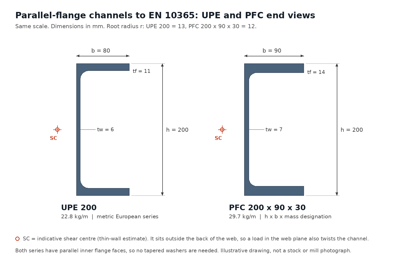
S275JR Parallel-Flange Channels: What the Order Covers
Gangsteel supplies EN 10025-2 S275JR channels in the UPE and PFC series for secondary framing that is strength-governed but does not need low-temperature toughness: trimmer and edge beams, lintels formed from paired channels, crane-girder surge members, purlins and side rails, and truss members in buildings. PFC tables in European and UK design data are commonly published in S275 and S355, so S275JR is often the default grade where a design uses PFC sizes. Typical order wording: “PFC 260 × 90 × 35, EN 10025-2 S275JR”.
| Item | Value | Note |
|---|---|---|
| Material | EN 10025-2:2019 S275JR (1.0044) | Impact quality 27 J at +20 °C |
| Section series | UPE and PFC to EN 10365 | Both have parallel inner flange faces; UPN (tapered flange) is a different series |
| Tolerances | EN 10279 | Channel-specific tolerances on dimensions, shape and mass |
| General delivery | EN 10025-1 | Testing, inspection documents, marking |
| Supply | Gangsteel supplies EN 10025-2 S275JR UPE and PFC channels | Sizes, quantities and stock confirmed per enquiry |
| Former designation | St 44-2 (DIN 17100, withdrawn) | Historical only |
UPE Channels in S275JR
| Section | h mm | b mm | tw mm | tf mm | kg/m | ReH MPa | Iy cm⁴ | Wel,y cm³ | Wel,z cm³ | Wel,y·ReH kNm | Class, axial |
|---|---|---|---|---|---|---|---|---|---|---|---|
| UPE 80 | 80 | 50 | 4.0 | 7.0 | 7.9 | 275 | 107 | 26.8 | 8 | 7 | Class 1 |
| UPE 100 | 100 | 55 | 4.5 | 7.5 | 9.8 | 275 | 207 | 41.4 | 11 | 11 | Class 1 |
| UPE 120 | 120 | 60 | 5.0 | 8.0 | 12.1 | 275 | 364 | 60.6 | 14 | 17 | Class 1 |
| UPE 140 | 140 | 65 | 5.0 | 9.0 | 14.5 | 275 | 600 | 85.6 | 18 | 24 | Class 1 |
| UPE 160 | 160 | 70 | 5.5 | 9.5 | 17.0 | 275 | 911 | 114 | 23 | 31 | Class 1 |
| UPE 180 | 180 | 75 | 5.5 | 10.5 | 19.7 | 275 | 1,350 | 150 | 29 | 41 | Class 1 |
| UPE 200 | 200 | 80 | 6.0 | 11.0 | 22.8 | 275 | 1,910 | 191 | 35 | 53 | Class 1 |
| UPE 220 | 220 | 85 | 6.5 | 12.0 | 26.6 | 275 | 2,680 | 244 | 43 | 67 | Class 1 |
| UPE 240 | 240 | 90 | 7.0 | 12.5 | 30.2 | 275 | 3,600 | 300 | 50 | 82 | Class 1 |
| UPE 270 | 270 | 95 | 7.5 | 13.5 | 35.2 | 275 | 5,250 | 389 | 61 | 107 | Class 1 |
| UPE 300 | 300 | 100 | 9.5 | 15.0 | 44.4 | 275 | 7,820 | 522 | 76 | 144 | Class 1 |
| UPE 330 | 330 | 105 | 11.0 | 16.0 | 53.2 | 275 | 11,000 | 667 | 90 | 183 | Class 1 |
| UPE 360 | 360 | 110 | 12.0 | 17.0 | 61.2 | 265 | 14,800 | 824 | 105 | 218 | Class 1 |
| UPE 400 | 400 | 115 | 13.5 | 18.0 | 72.2 | 265 | 21,000 | 1,050 | 123 | 278 | Class 1 |
PFC Channels in S275JR
| Section | h mm | b mm | tw mm | tf mm | kg/m | ReH MPa | Iy cm⁴ | Wel,y cm³ | Wel,z cm³ | Wel,y·ReH kNm | Class, axial |
|---|---|---|---|---|---|---|---|---|---|---|---|
| PFC 100 × 50 × 10 | 100 | 50 | 5.0 | 8.5 | 10.2 | 275 | 208 | 41.5 | 10 | 11 | Class 1 |
| PFC 125 × 65 × 15 | 125 | 65 | 5.5 | 9.5 | 14.8 | 275 | 483 | 77.3 | 19 | 21 | Class 1 |
| PFC 150 × 75 × 18 | 150 | 75 | 5.5 | 10.0 | 17.9 | 275 | 861 | 115 | 27 | 32 | Class 1 |
| PFC 150 × 90 × 24 | 150 | 90 | 6.5 | 12.0 | 23.9 | 275 | 1,160 | 155 | 44 | 43 | Class 1 |
| PFC 180 × 75 × 20 | 180 | 75 | 6.0 | 10.5 | 20.3 | 275 | 1,370 | 152 | 29 | 42 | Class 1 |
| PFC 180 × 90 × 26 | 180 | 90 | 6.5 | 12.5 | 26.1 | 275 | 1,820 | 202 | 47 | 56 | Class 1 |
| PFC 200 × 75 × 23 | 200 | 75 | 6.0 | 12.5 | 23.4 | 275 | 1,960 | 196 | 34 | 54 | Class 1 |
| PFC 200 × 90 × 30 | 200 | 90 | 7.0 | 14.0 | 29.7 | 275 | 2,520 | 252 | 53 | 69 | Class 1 |
| PFC 230 × 75 × 26 | 230 | 75 | 6.5 | 12.5 | 25.7 | 275 | 2,750 | 239 | 35 | 66 | Class 1 |
| PFC 230 × 90 × 32 | 230 | 90 | 7.5 | 14.0 | 32.2 | 275 | 3,520 | 306 | 55 | 84 | Class 1 |
| PFC 260 × 75 × 28 | 260 | 75 | 7.0 | 12.0 | 27.6 | 275 | 3,620 | 278 | 34 | 76 | Class 1 |
| PFC 260 × 90 × 35 | 260 | 90 | 8.0 | 14.0 | 34.8 | 275 | 4,730 | 364 | 56 | 100 | Class 1 |
| PFC 300 × 90 × 41 | 300 | 90 | 9.0 | 15.5 | 41.4 | 275 | 7,220 | 481 | 63 | 132 | Class 1 |
| PFC 300 × 100 × 46 | 300 | 100 | 9.0 | 16.5 | 45.5 | 265 | 8,230 | 549 | 82 | 145 | Class 1 |
| PFC 380 × 100 × 54 | 380 | 100 | 9.5 | 17.5 | 54.0 | 265 | 15,000 | 791 | 89 | 210 | Class 2 |
| PFC 430 × 100 × 64 | 430 | 100 | 11.0 | 19.0 | 64.4 | 265 | 21,900 | 1,020 | 98 | 270 | Class 2 |
The same five sizes (UPE 360 (17.0 mm), UPE 400 (18.0 mm), PFC 300 × 100 × 46 (16.5 mm), PFC 380 × 100 × 54 (17.5 mm) and PFC 430 × 100 × 64 (19.0 mm)) drop from 275 to 265 MPa because their flanges exceed 16 mm. At ε = 0.92 the UPE series stays Class 1 in pure compression throughout, while the two deepest PFC sizes, 380 × 100 × 54 and 430 × 100 × 64, become Class 2 in compression because their webs are slender (c/t about 33). That still lets the full plastic resistance be used; in bending every size is Class 1.
Wel,y·ReH is the characteristic elastic moment about the major axis using the S275JR yield band for that flange thickness. It is a cross-section value only, with no partial factor, no allowance for lateral-torsional buckling, and no allowance for the torsion that arises whenever a channel is loaded away from its shear centre, so it is not a safe working load. The axial class uses the EN 1993-1-1 limits for internal webs (33/38/42ε) and outstand flanges (9/10/14ε) with ε = √(235/ReH). Under pure major-axis bending every UPE and PFC size in this grade is Class 1. Confirm classification against the design code and national annex for the project.
S275JR Chemistry for Channel Sections
| Element | Limit |
|---|---|
| C | 0.21 |
| Mn | 1.50 |
| Si | no maximum in grade row |
| P | 0.040 |
| S | 0.040 |
| N | 0.012 (waived with total Al ≥ 0.020% or reported N-binding elements) |
| Cu | 0.55 |
| CEV | 0.40 |
S275JR permits 0.21% carbon and a CEV of 0.40%, a step up from S235JR that remains comfortable for welding channel webs and flanges up to 19 mm. Silicon is not capped in the grade row, so state the galvanizing silicon option if hot-dip coating is planned.
S275JR Tensile and Impact Requirements
| Property | tf ≤ 16 mm | 16 mm < tf ≤ 40 mm |
|---|---|---|
| Minimum ReH | 275 MPa | 265 MPa |
| Rm | 410–560 MPa | 410–560 MPa |
| Minimum A (L0 = 5.65√S0) | 23% | 23% |
| Charpy V, minimum | 27 J at +20 °C | 27 J at +20 °C |
| Channels in this band | UPE 80–330; PFC 100 × 50 to 300 × 90 | UPE 360, UPE 400; PFC 300 × 100, 380 × 100, 430 × 100 |
The +20 °C, 27 J test suits enclosed or heated buildings. For unheated structures, canopies or cold stores the S275J0 or S275J2 qualities are separate grades with their own impact temperatures; they are not interchangeable with S275JR on a certificate.
Designing with S275JR Channels
S275JR gives a 17% higher yield than S235JR with only a modest change in chemistry, which makes it a useful middle grade for channels whose resistance is checked rather than their deflection. Approximate elastic moments: UPE 240 about 83 kNm (300 cm³ × 275 MPa), PFC 260 × 90 × 35 about 100 kNm. In practice the torsion caused by eccentric load (the shear centre is outside the web) and lateral-torsional buckling often decide channel sizes, so the gain is realised mainly when the compression flange and the load point are restrained.
For lintels, two channels bolted back-to-back with spacers carry masonry symmetrically; a single channel supporting brickwork on one flange needs a torsion check or restraint from the wall ties. In side-rail and purlin systems, place the channel with the toes toward the direction that keeps the cladding load closest to the shear centre, or provide anti-sag bars.
S275JR Compared with Other Channel Grades
| Grade | UPE 300 Wel,y·ReH | PFC 430 × 100 × 64 Wel,y·ReH | Axial class of PFC 430 |
|---|---|---|---|
| S235JR | about 123 kNm | about 230 kNm | Class 1 |
| S275JR | about 144 kNm | about 270 kNm | Class 2 |
| S355JR / S355J2 | about 185 kNm | about 352 kNm | Class 3 |
Fabrication: Connections, Welding and Coating
Welding is routine: with CEV ≤ 0.40% preheat is usually needed only for heavily restrained joints in the thicker PFC flanges or in cold conditions. Parallel flanges take flat washers. Where channels are coped to fit into HEA or IPE beams, the root radius (up to 18 mm on UPE 360–400 and 15 mm on large PFC) defines the minimum cope radius and clearance. Prime or galvanize after drilling; seal back-to-back gaps to avoid trapped moisture.
Delivery Condition, Inspection and Lead Time
| Item | Specify | Reason |
|---|---|---|
| Series and size | UPE 220 or PFC 230 × 90 × 32, never just “220 channel” | UPE, PFC and UPN of similar depth differ in width, thickness and mass |
| Delivery condition | +AR or +N where required | Not implied by the grade name |
| Impact test | Whether the 27 J at +20 °C result must be reported, and specimen size for thin flanges | Channel flanges are 7–19 mm thick |
| Inspection document | EN 10204 3.1 for heat-specific results | Traceability to the delivered pieces |
| Dimensions | EN 10279 tolerances, lengths, cut list | Nominal values are not tolerances |
| Mass basis | Theoretical or weighed | Avoids invoicing disputes |
Lead time: typical delivery is about 35 days for mill orders, and sizes available from stock can ship in 1–3 days. Stock is confirmed size by size at enquiry; the UPE and PFC tables on this page are reference geometry, not a stock list.
RFQ Checklist
- Series and full designation (UPE or PFC), quantity and lengths.
- EN 10025-2 S275JR, delivery condition and any chemistry options such as the galvanizing silicon range.
- Impact verification and EN 10204 document type.
- Processing: sawing, drilling or punching of web and flanges, blasting, priming, galvanizing.
- Packing, marking and destination; whether stock sizes for 1–3 day dispatch are preferred over a mill order.
Primary members in the same grade are covered by EN 10025-2 S275JR HEA and HEB beams and EN 10025-2 S275JR IPE beams. The parallel flange channel size range and grade overview summarises PFC across grades, gusset and end plates are covered by EN 10025-2 S275JR steel plate, and the structural steel sections guide compares all section families.
The same UPE and PFC channels in other EN 10025-2 grades: S235JR channels, S355JR channels, S355J2 channels.
Frequently Asked Questions
Which S275JR channels are rated at 265 MPa?
The five sizes with flanges over 16 mm: UPE 360, UPE 400, and PFC 300 × 100 × 46, 380 × 100 × 54 and 430 × 100 × 64. All others are rated at 275 MPa.
Why do the largest PFC channels become Class 2 in S275JR?
Their webs have a depth-to-thickness ratio of about 33. At 265 MPa the Class 1 limit for an internal compression part is 33ε, about 31.0, so the web falls in Class 2. Class 2 still permits the plastic resistance; it only limits rotation capacity for plastic hinge analysis.
Is S275JR the same as the old St 44-2?
S275JR is the EN 10025-2 successor generally used where St 44-2 was specified under the withdrawn DIN 17100. Specify S275JR to EN 10025-2:2019 on new orders, as the certificate will show only the current designation.
Should I choose UPE or PFC for an S275JR trimmer beam?
Check which series your design data and connection details use. For equal depth, PFC is generally wider and heavier with thicker flanges; UPE is lighter. Both have parallel flanges and similar fabrication, but the section properties are not interchangeable.
Can S275JR channels be used outdoors?
Yes, with suitable corrosion protection, provided the design does not call for impact toughness below +20 °C. For cold exposed structures specify S275J0 or S275J2 instead.
How do I stop a single S275JR channel from twisting?
Bring the load as close as possible to the shear centre, restrain the member through the floor, roof or wall it supports, or pair two channels. Otherwise design for combined bending and torsion.
Does S275JR need preheat?
Rarely for channel thicknesses. A CEV maximum of 0.40% and flanges no thicker than 19 mm normally allow welding without preheat, but the welding procedure specification decides.
What lead time applies to S275JR UPE and PFC channels?
About 35 days for mill orders; stock sizes can ship in 1–3 days. Availability of each size is confirmed at enquiry.