


Steel Channels
EN 10025-2 S355J2 UPE and PFC Channels: Sizes & Data
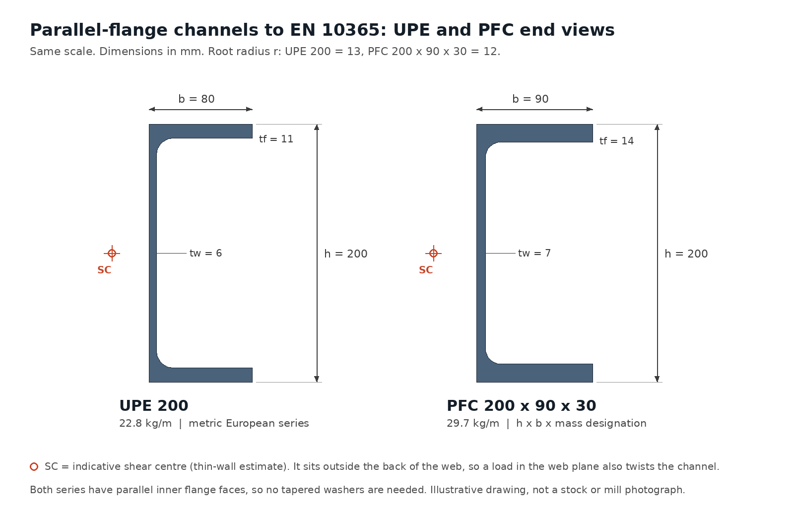
S355J2 Parallel-Flange Channels: What the Order Covers
S355J2 is the cold-impact quality of the 355 MPa structural grade: 27 J at −20 °C, fully killed, with tighter carbon, phosphorus and sulphur limits than S355JR. Gangsteel supplies EN 10025-2 S355J2 UPE and PFC channels for exposed steelwork, canopies, transport and handling frames, platforms and secondary members of bridges and offshore-adjacent structures where the fabrication specification demands notch toughness. Order as “UPE 330, EN 10025-2 S355J2” or “PFC 180 × 90 × 26, EN 10025-2 S355J2”, and add +N if a normalized or normalized-rolled condition is required.
| Item | Value | Note |
|---|---|---|
| Material | EN 10025-2:2019 S355J2 (1.0577) | Impact quality 27 J at −20 °C |
| Section series | UPE and PFC to EN 10365 | Both have parallel inner flange faces; UPN (tapered flange) is a different series |
| Tolerances | EN 10279 | Channel-specific tolerances on dimensions, shape and mass |
| General delivery | EN 10025-1 | Testing, inspection documents, marking |
| Supply | Gangsteel supplies EN 10025-2 S355J2 UPE and PFC channels | Sizes, quantities and stock confirmed per enquiry |
| Former designation | St 52-3 N (DIN 17100, withdrawn) | Historical only |
UPE Channels in S355J2
| Section | h mm | b mm | tw mm | tf mm | kg/m | ReH MPa | Iy cm⁴ | Wel,y cm³ | Wel,z cm³ | Wel,y·ReH kNm | Class, axial | Charpy specimen, indicative |
|---|---|---|---|---|---|---|---|---|---|---|---|---|
| UPE 80 | 80 | 50 | 4.0 | 7.0 | 7.9 | 355 | 107 | 26.8 | 8 | 10 | Class 1 | 5 mm sub-size |
| UPE 100 | 100 | 55 | 4.5 | 7.5 | 9.8 | 355 | 207 | 41.4 | 11 | 15 | Class 1 | 5 mm sub-size |
| UPE 120 | 120 | 60 | 5.0 | 8.0 | 12.1 | 355 | 364 | 60.6 | 14 | 22 | Class 1 | 7.5 mm sub-size |
| UPE 140 | 140 | 65 | 5.0 | 9.0 | 14.5 | 355 | 600 | 85.6 | 18 | 30 | Class 1 | 7.5 mm sub-size |
| UPE 160 | 160 | 70 | 5.5 | 9.5 | 17.0 | 355 | 911 | 114 | 23 | 40 | Class 1 | 7.5 mm sub-size |
| UPE 180 | 180 | 75 | 5.5 | 10.5 | 19.7 | 355 | 1,350 | 150 | 29 | 53 | Class 1 | 7.5 mm sub-size |
| UPE 200 | 200 | 80 | 6.0 | 11.0 | 22.8 | 355 | 1,910 | 191 | 35 | 68 | Class 1 | Full-size |
| UPE 220 | 220 | 85 | 6.5 | 12.0 | 26.6 | 355 | 2,680 | 244 | 43 | 87 | Class 1 | Full-size |
| UPE 240 | 240 | 90 | 7.0 | 12.5 | 30.2 | 355 | 3,600 | 300 | 50 | 106 | Class 1 | Full-size |
| UPE 270 | 270 | 95 | 7.5 | 13.5 | 35.2 | 355 | 5,250 | 389 | 61 | 138 | Class 2 | Full-size |
| UPE 300 | 300 | 100 | 9.5 | 15.0 | 44.4 | 355 | 7,820 | 522 | 76 | 185 | Class 1 | Full-size |
| UPE 330 | 330 | 105 | 11.0 | 16.0 | 53.2 | 355 | 11,000 | 667 | 90 | 237 | Class 1 | Full-size |
| UPE 360 | 360 | 110 | 12.0 | 17.0 | 61.2 | 345 | 14,800 | 824 | 105 | 284 | Class 1 | Full-size |
| UPE 400 | 400 | 115 | 13.5 | 18.0 | 72.2 | 345 | 21,000 | 1,050 | 123 | 362 | Class 1 | Full-size |
PFC Channels in S355J2
| Section | h mm | b mm | tw mm | tf mm | kg/m | ReH MPa | Iy cm⁴ | Wel,y cm³ | Wel,z cm³ | Wel,y·ReH kNm | Class, axial | Charpy specimen, indicative |
|---|---|---|---|---|---|---|---|---|---|---|---|---|
| PFC 100 × 50 × 10 | 100 | 50 | 5.0 | 8.5 | 10.2 | 355 | 208 | 41.5 | 10 | 15 | Class 1 | 7.5 mm sub-size |
| PFC 125 × 65 × 15 | 125 | 65 | 5.5 | 9.5 | 14.8 | 355 | 483 | 77.3 | 19 | 27 | Class 1 | 7.5 mm sub-size |
| PFC 150 × 75 × 18 | 150 | 75 | 5.5 | 10.0 | 17.9 | 355 | 861 | 115 | 27 | 41 | Class 1 | 7.5 mm sub-size |
| PFC 150 × 90 × 24 | 150 | 90 | 6.5 | 12.0 | 23.9 | 355 | 1,160 | 155 | 44 | 55 | Class 1 | Full-size |
| PFC 180 × 75 × 20 | 180 | 75 | 6.0 | 10.5 | 20.3 | 355 | 1,370 | 152 | 29 | 54 | Class 1 | 7.5 mm sub-size |
| PFC 180 × 90 × 26 | 180 | 90 | 6.5 | 12.5 | 26.1 | 355 | 1,820 | 202 | 47 | 72 | Class 1 | Full-size |
| PFC 200 × 75 × 23 | 200 | 75 | 6.0 | 12.5 | 23.4 | 355 | 1,960 | 196 | 34 | 70 | Class 1 | Full-size |
| PFC 200 × 90 × 30 | 200 | 90 | 7.0 | 14.0 | 29.7 | 355 | 2,520 | 252 | 53 | 89 | Class 1 | Full-size |
| PFC 230 × 75 × 26 | 230 | 75 | 6.5 | 12.5 | 25.7 | 355 | 2,750 | 239 | 35 | 85 | Class 2 | Full-size |
| PFC 230 × 90 × 32 | 230 | 90 | 7.5 | 14.0 | 32.2 | 355 | 3,520 | 306 | 55 | 109 | Class 1 | Full-size |
| PFC 260 × 75 × 28 | 260 | 75 | 7.0 | 12.0 | 27.6 | 355 | 3,620 | 278 | 34 | 99 | Class 2 | Full-size |
| PFC 260 × 90 × 35 | 260 | 90 | 8.0 | 14.0 | 34.8 | 355 | 4,730 | 364 | 56 | 129 | Class 1 | Full-size |
| PFC 300 × 90 × 41 | 300 | 90 | 9.0 | 15.5 | 41.4 | 355 | 7,220 | 481 | 63 | 171 | Class 2 | Full-size |
| PFC 300 × 100 × 46 | 300 | 100 | 9.0 | 16.5 | 45.5 | 345 | 8,230 | 549 | 82 | 189 | Class 1 | Full-size |
| PFC 380 × 100 × 54 | 380 | 100 | 9.5 | 17.5 | 54.0 | 345 | 15,000 | 791 | 89 | 273 | Class 3 | Full-size |
| PFC 430 × 100 × 64 | 430 | 100 | 11.0 | 19.0 | 64.4 | 345 | 21,900 | 1,020 | 98 | 352 | Class 3 | Full-size |
Yield bands match S355JR: 355 MPa up to 16 mm flange thickness and 345 MPa for UPE 360 (17.0 mm), UPE 400 (18.0 mm), PFC 300 × 100 × 46 (16.5 mm), PFC 380 × 100 × 54 (17.5 mm) and PFC 430 × 100 × 64 (19.0 mm). The section-class results are therefore also the same: UPE 270, PFC 230 × 75, 260 × 75 and 300 × 90 are Class 2 in pure compression, PFC 380 × 100 and 430 × 100 are Class 3, and all sizes are Class 1 in bending. What distinguishes S355J2 is toughness and chemistry, not strength.
Wel,y·ReH is the characteristic elastic moment about the major axis using the S355J2 yield band for that flange thickness. It is a cross-section value only, with no partial factor, no allowance for lateral-torsional buckling, and no allowance for the torsion that arises whenever a channel is loaded away from its shear centre, so it is not a safe working load. The axial class uses the EN 1993-1-1 limits for internal webs (33/38/42ε) and outstand flanges (9/10/14ε) with ε = √(235/ReH). Under pure major-axis bending every UPE and PFC size in this grade is Class 1. Confirm classification against the design code and national annex for the project.
S355J2 Chemistry for Channel Sections
| Element | Limit |
|---|---|
| C | 0.20 |
| Mn | 1.60 |
| Si | 0.55 |
| P | 0.030 |
| S | 0.030 |
| N | no maximum; fully killed with N-binding elements (e.g. Al ≥ 0.02%), reported |
| Cu | 0.55 |
| CEV | 0.45 |
Carbon is limited to 0.20% (versus 0.24% for S355JR), phosphorus and sulphur to 0.030% each, and the steel must be fully killed with nitrogen-binding elements, which improves weld-zone toughness. CEV remains 0.45% maximum for all channel thicknesses.
S355J2 Tensile and Impact Requirements
| Property | tf ≤ 16 mm | 16 mm < tf ≤ 40 mm |
|---|---|---|
| Minimum ReH | 355 MPa | 345 MPa |
| Rm | 470–630 MPa | 470–630 MPa |
| Minimum A (L0 = 5.65√S0) | 22% | 22% |
| Charpy V, minimum | 27 J at −20 °C | 27 J at −20 °C |
| Channels in this band | UPE 80–330; PFC 100 × 50 to 300 × 90 | UPE 360, UPE 400; PFC 300 × 100, 380 × 100, 430 × 100 |
The Charpy test at −20 °C uses a full-size 10 × 10 mm specimen only where the flange is thick enough. Channel flanges run from 7.0 mm (UPE 80) to 19.0 mm (PFC 430), so the column “Charpy specimen, indicative” in the tables shows which sizes allow a full-size specimen (flanges about 11 mm and over), which need a 7.5 mm sub-size specimen, and where a 5 mm specimen applies. EN 10025-1/-2 set the reduced energy values for sub-size specimens; agree in the order how small sizes are to be tested and reported.
Designing with S355J2 Channels
For exposed channels the governing check is often not strength but brittle-fracture safety for the lowest service temperature and the element thickness, which is why S355J2 is specified even for modest members. The structural behaviour matches S355JR: UPE 330 gives about 237 kNm (667 cm³ × 355 MPa) and PFC 180 × 90 × 26 about 72 kNm as characteristic elastic moments, both before any torsion or buckling reduction.
Channels in exposed frames usually carry wind and access loads applied eccentrically to the shear centre. Pair them, restrain them through grating or deck connections, or design for warping torsion. Where channels act as stringers for stairs or walkways in cold climates, the welded tread connections are the critical details for toughness.
S355J2 Compared with Other Channel Grades
| Grade | Charpy V | C max | P / S max |
|---|---|---|---|
| S235JR | 27 J at +20 °C | 0.17% | 0.040% / 0.040% |
| S275JR | 27 J at +20 °C | 0.21% | 0.040% / 0.040% |
| S355JR | 27 J at +20 °C | 0.24% | 0.040% / 0.040% |
| S355J2 | 27 J at −20 °C | 0.20% | 0.030% / 0.030% |
Fabrication: Connections, Welding and Coating
S355J2 channels are welded to qualified procedures with low-hydrogen consumables whose weld metal also meets the −20 °C impact requirement. Preheat depends on CEV, combined thickness and hydrogen scale. Thermal cutting of flanges is acceptable; grind hardened edges where the execution standard requires it. For hot-dip galvanizing, specify silicon and phosphorus ranges and avoid high residual stresses at copes, which can crack in the zinc bath.
Delivery Condition, Inspection and Lead Time
| Item | Specify | Reason |
|---|---|---|
| Series and size | UPE 220 or PFC 230 × 90 × 32, never just “220 channel” | UPE, PFC and UPN of similar depth differ in width, thickness and mass |
| Delivery condition | +AR or +N where required | Not implied by the grade name |
| Impact test | Whether the 27 J at −20 °C result must be reported, and specimen size for thin flanges | Channel flanges are 7–19 mm thick |
| Inspection document | EN 10204 3.1 for heat-specific results | Traceability to the delivered pieces |
| Dimensions | EN 10279 tolerances, lengths, cut list | Nominal values are not tolerances |
| Mass basis | Theoretical or weighed | Avoids invoicing disputes |
Lead time: typical delivery is about 35 days for mill orders, and sizes available from stock can ship in 1–3 days. Stock is confirmed size by size at enquiry; the UPE and PFC tables on this page are reference geometry, not a stock list.
RFQ Checklist
- Series and full designation (UPE or PFC), quantity and lengths.
- EN 10025-2 S355J2, delivery condition and any chemistry options such as the galvanizing silicon range.
- Impact verification and EN 10204 document type.
- Processing: sawing, drilling or punching of web and flanges, blasting, priming, galvanizing.
- Packing, marking and destination; whether stock sizes for 1–3 day dispatch are preferred over a mill order.
Primary members in the same grade are covered by EN 10025-2 S355J2 HEA and HEB beams and EN 10025-2 S355J2 IPE beams. The parallel flange channel size range and grade overview summarises PFC across grades, gusset and end plates are covered by EN 10025-2 S355J2 steel plate, and the structural steel sections guide compares all section families.
The same UPE and PFC channels in other EN 10025-2 grades: S235JR channels, S275JR channels, S355JR channels.
Frequently Asked Questions
What is the difference between S355J2 and S355JR channels?
Strength is identical. S355J2 is impact-tested at −20 °C rather than +20 °C, is fully killed, and has lower limits for carbon (0.20%), phosphorus and sulphur (0.030%).
Can a full-size Charpy specimen be taken from every S355J2 channel?
No. Flanges below about 11 mm, such as UPE 80–180 and PFC 100 × 50 to 180 × 75, only allow sub-size specimens, and the thinnest may need a 5 mm specimen. The applicable rules and reduced energy values are in EN 10025-1/-2; specify the testing approach in the order.
Which S355J2 channels are Class 3 in pure compression?
PFC 380 × 100 × 54 and PFC 430 × 100 × 64. UPE 270, PFC 230 × 75, 260 × 75 and 300 × 90 are Class 2. All sizes are Class 1 in major-axis bending.
Should S355J2 channels be ordered +N?
Only if the design or fabrication specification requires the normalized or normalized-rolled condition, for example where post-weld forming or hot working is planned. Otherwise +AR is common; the condition must be stated because the grade name does not imply it.
Is S355J2 the same as St 52-3 N?
It is the EN 10025-2 replacement generally used for that withdrawn DIN 17100 grade. New certificates will show EN 10025-2:2019 S355J2.
Do the impact requirements change for flanges over 16 mm?
No. The 27 J at −20 °C requirement applies across the channel thickness range; only the yield strength drops to 345 MPa above 16 mm.
Why do cold-climate projects specify S355J2 for small channels?
Brittle fracture depends on toughness, thickness, stress and service temperature, not just member size. Small exposed channels with welded attachments can be critical details, so codes often require a J2 quality.
What lead time applies to S355J2 UPE and PFC channels?
About 35 days for mill orders, and 1–3 days for stock sizes. The impact test reporting for sub-size specimens should be agreed before the mill order is placed.